The GMSType provides information about the Geometric Measurement System itself. It is the entry point to the OPC UA interface of a Geometric Measurement System. There is a basic structure to the interface. An instance of this type aggregates all information related to one system.
All instances of GMSType have to be referenced from the 3:Machines node defined in OPC 40001-1. At least one instance of GMSType shall be present to qualify for any profile of OPC UA for GMS.
The GMSType is formally defined in Table 12.
|
Attribute |
Value |
||||
|
BrowseName |
GMSType |
||||
|
IsAbstract |
False |
||||
|
References |
Node Class |
BrowseName |
DataType |
TypeDefinition |
Other |
|
Subtype of the MachineToolType defined in OPC UA for Machine Tools i.e. inheriting the InstanceDeclarations of that Node. |
|||||
|
0:HasComponent |
Object |
5:Equipment |
|
GMSEquipmentType |
0:Mandatory |
|
0:HasAddIn |
Object |
2:Identification |
|
GMSIdentificationType |
0:Mandatory |
|
0:HasComponent |
Object |
5:Notification |
|
5:NotificationType |
0:Mandatory |
|
0:HasComponent |
Object |
5:Production |
|
5:ProductionType |
0:Mandatory |
|
0:HasComponent |
Object |
ResultManagement |
|
GMSResultManagementType |
0:Mandatory |
|
0:HasComponent |
Object |
5:Monitoring |
|
GMSMonitoringType |
0:Mandatory |
|
Conformance Units |
|||||
|
GMS GMSType |
|||||
Equipment (see 8.6), Identification (see 8.7), Monitoring (see 8.8), Notification (see OPC UA 40501-1) and Production (see 8.9) are instances of the respective types. They are used to thematically assign the structure of the information in the MachineToolType and the GMSType, respectively. ResultManagement is the entry point for the result management.
The components of the GMSType have additional subcomponents that are defined in Table 13.
Table 13 – GMSType Additional Subcomponents
|
BrowsePath |
References |
NodeClass |
BrowseName |
DataType |
TypeDefinition |
Others |
||
|
0:HasComponent |
Object |
Calibration |
|
CalibrationPrognosisType |
0:Optional |
The MultiSensorType provides information about the type of measuring probe.
The MultiSensorType is formally defined in Table 14.
Table 14 – MultiSensorType Definition
|
Attribute |
Value |
||||
|
BrowseName |
MultiSensorType |
||||
|
IsAbstract |
False |
||||
|
References |
Node Class |
BrowseName |
DataType |
TypeDefinition |
Other |
|
Subtype of the MultiToolType defined in OPC UA for Machine Tools i.e. inheriting the InstanceDeclarations of that Node. |
|||||
|
0:HasProperty |
Variable |
Alignment |
ToolAlignmentState |
0:PropertyType |
0:Optional |
|
0:HasProperty |
Variable |
Axes |
0:String[] |
0:PropertyType |
0:Optional
|
|
0:HasComponent |
Object |
5:<Tool> |
|
SensorType |
0:OptionalPlaceholder |
|
Conformance Units |
|||||
|
MultiSensorType |
|||||
Axes describes the number and name (e.g., X,Y,Z) of available axes. The names of the axes should be described according to ISO 841 / ISO 10791.
Alignment describes if a tool is fixed or flexible.
The SensorType provides information about the properties of the sensor.
The SensorType is formally defined in Table 15.
Table 15 – SensorType Definition
|
Attribute |
Value |
||||
|
BrowseName |
SensorType |
||||
|
IsAbstract |
False |
||||
|
References |
Node Class |
BrowseName |
DataType |
TypeDefinition |
Other |
|
Subtype of the ToolType defined in OPC UA for Machine Tools inheriting the InstanceDeclarations of that Node. |
|||||
|
0:HasProperty |
Variable |
AbsoluteProbe |
0:Boolean |
0:PropertyType |
0:Optional |
|
0:HasProperty |
Variable |
Alignment |
ToolAlignmentState |
0:PropertyType |
0:Optional |
|
0:HasProperty |
Variable |
Axes |
0:String[] |
0:PropertyType |
0:Optional
|
|
0:HasComponent |
Variable |
Capabilities |
0:UInteger[] |
0:MultiStateDiscreteType |
0:Optional |
|
0:HasComponent |
Variable |
Class |
0:UInteger |
0:MultiStateDiscreteType |
0:Mandatory |
|
0:HasProperty |
Variable |
EngineeringUnit |
0:EUInformation |
|
0:Optional |
|
0:HasProperty |
Variable |
IsQualifiedStatus |
ToolIsQualifiedStatus |
0:PropertyType |
0:Optional |
|
0:HasProperty |
Variable |
MeasuringRange |
0:Double |
0:PropertyType |
0:Optional |
|
0:HasProperty |
Variable |
Resolution |
0:Double |
0:PropertyType |
0:Optional |
|
0:HasProperty |
Variable |
WorkingRange |
0:Double |
0:PropertyType |
0:Optional |
|
The following nodes are overwritten from ToolType and the Modelling Rule changed to Mandatory |
|||||
|
0:HasComponent |
Object |
5:ToolLife |
|
0:BaseObjectType |
0:Mandatory |
|
Conformance Units |
|||||
|
SensorType |
|||||
AbsoluteProbe indicates if the sensor provides an absolute position directly after switching on. The sensor does not need a referencing or zeroing after the start up.
Axes describes the number of available axes. The names of the axes should be descripted according to ISO 841 / ISO 10791.
Alignment describes if a sensor is fixed or flexible.
Capabilities is defined as an array of tool capabilities (e.g., single point measurement, scanning measurement, contact measurement). This value must not be changed.
The Class indicates in which mode a sensor is operated. This value must not be changed (see Table 17)
For each quantity, an EngineeringUnit is defined as reference value. A measured value is a multiple of this unit.
IsQualifiedStatus is defined as the status of the tool qualification.
The MeasuringRange defines the part of the working range for which the errors do not exceed the specified error limits. This is also called as "used range".
The Resolution indicates the smallest perceptible difference.
WorkingRange is the maximum range in which a probe can deliver values. It is normally larger than measuring range.
The components of the SensorType have additional subcomponents which are defined in Table 16.
Table 16 – SensorType Additional Subcomponents
|
BrowsePath |
References |
NodeClass |
BrowseName |
DataType |
TypeDefinition |
Others |
|
|
0:HasComponent |
Variable |
Qualified |
0:Double |
5:ToolLifeType |
0:Optional |
The 0:EngineeringUnits of Qualified must be a time unit (e.g., hour, days) and the StartValue is the timestamp (Unix timestamp) of the last qualification.
LimitValue is the chosen value at which the tool is no longer qualified.
WarningValue is the chosen value at which a warning is sent, that the sensor must be requalified.
The component Variables of the SensorType have specific Attribute values defined in Table 17. The Attribute values for Capabilities/0:EnumStrings and Class/0:EnumStrings given here shall be used by instances must not be changed.
Table 17 – SensorType Attribute values for child Nodes
|
BrowsePath |
Value Attribute |
Description Attribute |
|||
|
OtherPtMeasPtMeasSelfCenterFeatureExtractProfileScanArealScan |
|
|||
|
OtherNoToolUnDefToolTactileTouchTriggerTactileMeasuringOptical-1DOptical-2DOptical-3DRoughnessEddy Current SensorTemperatureProbingPtMeas |
|
|||
|
0 |
|
|||
|
True |
|
The element entries to the value attribute of Capabilities/0:EnumStrings have the following meaning:
Other: None of the entries defined applies.
PtMeas: Sensor capable to do single point measurement.
PtMeasSelfCenter: Sensor capable to do single point self-centering measurement.
FeatureExtract: Sensor capable to extract parameters of feature from recorded points.
ProfileScan: Sensor capable to record continuously points along a spatial path.
ArealScan: Sensor capable to record continuously lines with points along a spatial path.
The element entries to the value attribute of Class/0:EnumStrings have the following meaning:
Other: None of the entries defined applies.
NoTool: No sensor for the GMS is currently available.
UnDefTool: The properties of the current sensor are not defined.
TactileTouchTrigger: The current sensor is a tactile sensor with touch trigger contact detection.
TactileMeasuring: The current sensor is a tactile sensor with measuring contact detection.
Optical-1D: The current sensor is an optical sensor for 1 dimension (e.g., point distance sensor).
Optical-2D: The current sensor is an optical sensor for 2 dimensions (e.g., camera).
Optical-3D: The current sensor is an optical sensor for 3 dimensions (e.g., fringe projection sensor).
Roughness: The current sensor measures surface texture.
Eddy Current Sensor: The current sensor measures eddy current.
TemperatureProbing: The current sensor measures temperature.
SensorType and MultiSensorType define a two-level structure to inform about the abilities of the available sensors on a GMS. The MultiSensorType offers the possibility of combining technically connected sensors (e.g. different sensors on a flexible carrier like an articulating carrier [ISO 10360-1]). It is not intended to provide complete information about the technical structure of all sensor components (e.g. information about each stylus of a tactile probe [ISO 10360-1]). Nevertheless it is possible to do so by defining each stylus as a sensor.
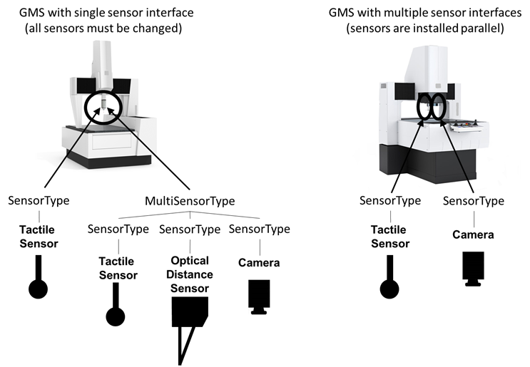
Figure 23 – Examples of sensor equipment and their representation in the OPC UA for GMS information model
Figure 23 shows two examples for GMSs with typical sensor equipment. The GMS on the left has a tactile sensor (e.g. fixed scanning sensor) and an articulating carrier described by the MultiSensorType with three further sensors, that are changeably connected to the same mount. The tactile sensor is modelled as SensorType; the MultiSensorType describing the articulating carrier combines three instances of SensorType. The GMS on the right has two sensors mounted in parallel, both are modelled as SensorTypes.
The LoadingMonitoringType provides information about the availability of the machine for loading a component for testing.
The LoadingMonitoringType is formally defined in Table 18.
Table 18 – LoadingMonitoringType Definition
|
Attribute |
Value |
||||
|
BrowseName |
LoadingMonitoringType |
||||
|
IsAbstract |
False |
||||
|
References |
Node Class |
BrowseName |
DataType |
TypeDefinition |
Other |
|
Subtype of the ElementMonitoringType defined in OPC UA for Machine Tools i.e. inheriting the InstanceDeclarations of that Node. |
|||||
|
0:HasComponent |
Variable |
IsInLoadingPosition |
0:Boolean |
0: TwoStateDiscreteType |
0:Optional |
|
0:HasComponent |
Variable |
LoadStatus |
0:UInteger |
0: MultiStateDiscreteType |
0:Mandatory |
|
Conformance Units |
|||||
|
GMS LoadingMonitoringType |
|||||
IsInLoadingPosition informs if the machine is in a safe position for loading.
LoadStatus contains information whether a part is loaded or not.
The component Variables of the SensorType have Attribute values defined in Table 19. The Attribute values given here shall be used by instances must not be changed.
Table 19 – LoadingMonitoringType Attribute Values for child Nodes
|
BrowsePath |
Value Attribute |
Description Attribute |
||
|
Unknown Empty Filled InProgress |
|
The element entries to the Attribute values of LoadStatus/0:EnumStrings have the following meaning:
Unknown: The load status is not known by the GMS.
Empty: There is no part in the GMS.
Filled: There is one or more parts in the GMS.
InProgess: The load status is changing.
The ToolMonitoringType provides the monitoring information about the active tool.
The ToolMonitoringType is formally defined in Table 20.
Table 20 – ToolMonitoringType Definition
|
Attribute |
Value |
||||
|
BrowseName |
ToolMonitoringType |
||||
|
IsAbstract |
False |
||||
|
References |
Node Class |
BrowseName |
DataType |
TypeDefinition |
Other |
|
Subtype of the WorkingUnitMonitoringType defined in OPC UA for Machine Tools i.e. inheriting the InstanceDeclarations of that Node. |
|||||
|
0:HasProperty |
Variable |
ActiveTool |
0:NodeId[] |
0:PropertyType |
0:Optional |
|
Conformance Units |
|||||
|
GMS ToolMonitoringType |
|||||
ActiveTool comprises all NodeIds of the tools which are currently used in the process.
The GMSEquipmentType provides information about the sensor or measuring probe.
The GMSEquipmentType is formally defined in Table 21.
Table 21 – GMSEquipmentType Definition
|
Attribute |
Value |
||||
|
BrowseName |
GMSEquipmentType |
||||
|
IsAbstract |
False |
||||
|
References |
Node Class |
BrowseName |
DataType |
TypeDefinition |
Other |
|
Subtype of the EquipmentType defined in OPC UA for Machine Tools i.e. inheriting the InstanceDeclarations of that Node. |
|||||
|
0:HasComponent |
Object |
AdditionalSensor |
|
0:FolderType |
0:Optional |
|
0:HasComponent |
Object |
Accessories |
|
0:FolderType |
0:Optional |
|
Conformance Units |
|||||
|
GMS GMSEquipmentType |
|||||
AdditionalSensor is a folder that contains all available additional sensors.
Accessories is a folder that contains all available accessories.
Table 22 – GMSEquipmentType Additional Subcomponents
|
BrowsePath |
References |
NodeClass |
BrowseName |
DataType |
TypeDefinition |
Others |
|
AdditionalSensor |
0:HasComponent |
Variable |
<AdditionalSensor> |
0:Number |
AdditionalSensorType |
0:OptionalPlaceholder |
|
Accessories |
0:HasComponent |
Object |
<RotaryTable> |
|
RotaryTableType |
0:OptionalPlaceholder |
|
Accessories |
0:HasComponent |
Object |
<SensorExchangeRack> |
|
SensorExchangeRackType |
0:OptionalPlaceholder |
|
Accessories |
0:HasComponent |
Object |
<TipExchangeRack> |
|
TipExchangeRackType |
0:OptionalPlaceholder |
<AdditionalSensor> represents individual additional sensors.
<RotaryTable> represents individual rotary tables.
<SensorExchangeRack> represents individual sensor exchange racks.
<TipExchangeRack> represents individual tip exchange racks.
The GMSIdentificationType provides information about the current machine.
The GMSIdentificationType is formally defined in Table 23.
Table 23 – GMSIdentificationType Definition
|
Attribute |
Value |
||||
|
BrowseName |
GMSIdentificationType |
||||
|
IsAbstract |
False |
||||
|
References |
Node Class |
BrowseName |
DataType |
TypeDefinition |
Other |
|
Subtype of the MachineToolIdentificationType defined in OPC UA for Machine Tools i.e. inheriting the InstanceDeclarations of that Node. |
|||||
|
0:HasProperty |
Variable |
SubDeviceClass |
0:String |
0:PropertyType |
0:Optional |
|
0:HasProperty |
Variable |
Workspace |
WorkspaceType |
0:PropertyType |
0:Optional |
|
Conformance Units |
|||||
|
GMS GMSIdentificationType |
|||||
SubDeviceClass is defined in a more special way than the generic DeviceClass. The classification is made based on the description in section 5.1.2. The corresponding possible values (for the SubDeviceClass) may be taken from Table 24.
Table 24 – Possible Values for DeviceClass and SubDeviceClass
|
DeviceClass |
SubDeviceClass |
|
ManualMeasurementDevice |
Caliper |
|
|
Micrometer |
|
|
Gauges |
|
|
SineBar |
|
|
Other |
|
SurfaceTextureMeasurementDevice |
RoughnessProfile |
|
|
RoughnessAreal |
|
|
Contour |
|
|
Other |
|
MultiPointMeasurementDevice |
StaticBenchGauge |
|
|
DynamicGaugingMachine |
|
|
MultiPointMeasurementPlugsForInnerAndOuterGeometries |
|
|
Other |
|
CoordinateMeasuringSystem |
CoordinateMeasuringMachine |
|
|
Optical3DCoordinateMeasuringSystem |
|
|
ArticulatingArm |
|
|
LaserTracker |
|
|
LaserRadar |
|
|
X-CT |
|
|
LaserTracer |
|
|
LightPenSystem |
|
|
Other |
|
SpecialGeometryMeasuringSystem |
RotaryAxisFormMeasuringInstrument |
|
|
GearMeasuringSystem |
|
|
ShaftMeasuringSystem |
|
|
Other |
|
Other |
Other |
Workspace is defined as the workspace of the axes, which is the same as the Measuring Range in most situations.
The GMSMonitoringType provides information about monitoring the status of the GMS.
The GMSMonitoringType is formally defined in Table 25.
Table 25 – GMSMonitoringType Definition
|
Attribute |
Value |
||||
|
BrowseName |
GMSMonitoringType |
||||
|
IsAbstract |
False |
||||
|
References |
Node Class |
BrowseName |
DataType |
TypeDefinition |
Other |
|
Subtype of the MonitoringType defined in OPC UA for Machine Tools i.e. inheriting the InstanceDeclarations of that Node. |
|||||
|
0:HasComponent |
Object |
LoadingMonitoring |
|
LoadingMonitoringType |
0:Optional
|
|
0:HasComponent |
Object |
ToolMonitoring |
|
ToolMonitoringType |
0:Optional
|
|
Conformance Units |
|||||
|
GMS GMSMonitoringType |
|||||
LoadingMonitoring informs if the machine is in a safe position for loading.
ToolMonitoring provides monitoring information about the tool (e.g., the currently used tool).
The GMSJobType provides aggregated production data to run a sequence of measurements of several parts after one preparatory mounting.
The GMSJobType is formally defined in Table 26.
Table 26 – GMSJobType Definition
|
Attribute |
Value |
||||
|
BrowseName |
GMSJobType |
||||
|
IsAbstract |
False |
||||
|
References |
Node Class |
BrowseName |
DataType |
TypeDefinition |
Other |
|
Subtype of the ProductionJobType defined in OPC UA for Machine Tools i.e. inheriting the InstanceDeclarations of that Node. |
|||||
|
0:HasProperty |
Variable |
BatchIdentifier |
0:String |
0:PropertyType |
0:Optional
|
|
0:HasProperty |
Variable |
Duration |
0:Duration |
0:PropertyType |
0:Optional
|
|
0:HasProperty |
Variable |
RemainingTime |
0:Duration |
0:PropertyType |
0:Optional
|
|
0:HasProperty |
Variable |
MeasurementReason |
MeasurementReasonEnum |
0:PropertyType |
0:Optional
|
|
Conformance Units |
|||||
|
GMS GMSJobType |
|||||
BatchIdentifier is defined as the unique batch identifier of the job for future reference.
Duration is defined as approximate time in milliseconds this job will take. This value can be estimated by the machine based on the last measurement runs or on the measuring equipment capability test.
RemainingTime is defined as the time in milliseconds remaining for the MeasuringRoutine and the part. It represents an approximated value that can't always be determined precisely.
MeasurementReason indicates why this job is carried out.
The GMSPartType provides information about the component to be measured by the GMS.
The GMSPartType is formally defined in Table 27.
Table 27 – GMSPartType Definition
|
Attribute |
Value |
||||
|
BrowseName |
GMSPartType |
||||
|
IsAbstract |
False |
||||
|
References |
Node Class |
BrowseName |
DataType |
TypeDefinition |
Other |
|
Subtype of the ProductionPartType defined in OPC UA for Machine Tools i.e. inheriting the InstanceDeclarations of that Node. |
|||||
|
0:HasComponent |
Variable |
NestIdentifier |
Number |
CatalogType |
0:Optional
|
|
0:HasComponent |
Variable |
Operator |
Number |
CatalogType |
0:Optional
|
|
0:HasProperty |
Variable |
PartAmendmentStatus |
0:String |
0:PropertyType |
0:Optional
|
|
0:HasComponent |
Variable |
PartCarrierIdentifier |
Number |
CatalogType |
0:Optional
|
|
0:HasProperty |
Variable |
PartDescription |
0:String |
0:PropertyType |
0:Optional
|
|
0:HasComponent |
Variable |
ProcessParameter |
Number[] |
CatalogType |
0:Optional
|
|
0:HasComponent |
Variable |
ProcessingMachineIdentifier |
Number |
CatalogType |
0:Optional
|
|
0:HasProperty |
Variable |
ProductionNumber |
0:String |
0:PropertyType |
0:Optional
|
|
Conformance Units |
|||||
|
GMS GMSPartType |
|||||
NestIdentifier indicates the nesting or spindle used to create or process the current part.
The operator specifies the worker who performs the measurement. The field contains an Identifier of the worker.
PartAmendmentStatus is used to distinguish and identify a version of the part type currently measured via a GMS.
PartCarrierIdentifier defines the unique identifier for the part carrier.
PartDescription is defined as a free text field that can be used for a customer part description.
ProcessParameter is defined as an additional parameter that describes the process.
ProcessingMachineIdentifier is a unique identifier of the machine that has processed the part.
ProductionNumber is a freely selectable identifier that identifies a subset of a production batch.
The CalibrationPrognosisType provides information about the GMS status regarding its performance. During the calibration the GMS’s errors are determined. The GMS performance is verified if the error is not greater than the specification. The information about the error is not used for correction. The GMS is not considered as a calibration target according to OPC 10000-200. Therefore a separate specification is defined here. The CalibrationPrognosisType is formally defined in Table 28.
Table 28 – CalibrationPrognosisType Definition
|
Attribute |
Value |
||||
|
BrowseName |
CalibrationPrognosisType |
||||
|
IsAbstract |
False |
||||
|
References |
Node Class |
BrowseName |
DataType |
TypeDefinition |
Other |
|
Subtype of the PrognosisType defined in OPC UA for Machine Tools i.e. inheriting the InstanceDeclarations of that Node. |
|||||
|
0:HasProperty |
Variable |
Calibrated |
0:Boolean |
0:PropertyType |
0:Mandatory
|
|
0:HasProperty |
Variable |
CalibrationInterval |
0:Duration |
0:PropertyType |
0:Optional
|
|
0:HasProperty |
Variable |
CalibrationPreptime |
0:Duration |
0:PropertyType |
0:Optional
|
|
0:HasProperty |
Variable |
DateOfCalibration |
0:UtcTime |
0:PropertyType |
0:Mandatory
|
|
0:HasProperty |
Variable |
CalibrationCertificate |
0:String[] |
0:PropertyType |
0:Optional |
|
Conformance Units |
|||||
|
GMS CalibrationPrognosisType |
|||||
Calibrated indicates whether the machine is calibrated or not.
CalibrationInterval is defined as the interval of time in which the machine needs a new calibration. The exact interval depends on the measuring principle and the machine utilization and is provided by the customer.
CalibrationPreptime is defined as the additional time needed to prepare a calibration considering the calibration interval to assure that the calibration expired (see Figure 24 for reference).
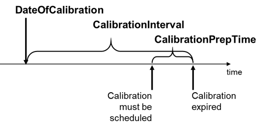
Figure 24 – Explanation for the difference between the calibration interval and the calibration preparation time.
DateOfCalibration is defined as the date and time when the last calibration was carried out.
CalibrationCertificate contains a reference to all available calibration certificates.
The GMSResultManagementType provides mechanisms to access results generated by the underlying GMS. Results can be managed in a local result store of the Server. Methods and Objects with Variables as well as Events and external file stores can be used to provide the results for the Client.
Figure 22 shows the hierarchical structure and details of the composition. It is formally defined in Table 29.
This ObjectType extends the ResultManagementType of the Machinery. As part of this extension, deviation values can be provided via OPC UA.
Table 29 – GMSResultManagementType Definition
|
Attribute |
Value |
||||
|
BrowseName |
GMSResultManagementType |
||||
|
IsAbstract |
False |
||||
|
References |
Node Class |
BrowseName |
DataType |
TypeDefinition |
Other |
|
Subtype of the ResultManagementType defined in OPC UA 10000-3 i.e. inheriting the InstanceDeclarations of that Node. |
|||||
|
0:HasComponent |
Object |
CorrectionsFolder |
|
0:FolderType |
0:Optional
|
|
0:GeneratesEvent |
ObjectType |
IntermediateResultEventType |
|
|
|
|
Conformance Units |
|||||
|
GMS ResultManagementType |
|||||
CorrectionsFolder is a folder that contains several corrections. The count and the corrections itself are application-specific.
The components of the GMSResultManagementType have additional subcomponents which are defined in Table 30.
Table 30 – GMSResultManagementType Additional Subcomponents
|
BrowsePath |
References |
NodeClass |
BrowseName |
DataType |
TypeDefinition |
Others |
|
CorrectionsFolder |
0:HasComponent |
Object |
<Corrections> |
|
CorrectionType |
0:OptionalPlaceholder |
|
CorrectionsFolder |
0:HasComponent |
Variable |
CorrectionCount |
Integer |
BaseDataVariableType |
0:Optional |
<Corrections> represents individual corrections.
CorrectionCount indicates the total number of corrections.
The CorrectionType provides information about a correction value the GMS has calculated. It is formally defined in Table 31. The value is the deviation of a characteristic value from a target value. The target value is a value the manufacturing should achieve. The correction can be used by a (tool) machine to adjust the production process. This can be, for example, the correction of a tool. Either the correction value relative or the correction value absolute must be implemented.
Table 31 – CorrectionType Definition
|
Attribute |
Value |
||||
|
BrowseName |
CorrectionType |
||||
|
IsAbstract |
False |
||||
|
References |
NodeClass |
BrowseName |
DataType |
TypeDefinition |
Other |
|
Subtype of the BaseObjectType defined in OPC 10000-3 |
|||||
|
0:HasProperty |
Variable |
Identifier |
0:String |
0:PropertyType |
0:Mandatory |
|
0:HasProperty |
Variable |
CharacteristicIdentifier |
0:String |
0:PropertyType |
0:Mandatory |
|
0:HasComponent |
Variable |
CorrectionValueRelative |
0:Double |
0:AnalogUnitType |
0:Optional |
|
0:HasComponent |
Variable |
CorrectionValueAbsolute |
0:Double |
0:AnalogUnitType |
0:Optional |
|
0:HasComponent |
Variable |
UpperControlLimit |
0:Double |
0:AnalogUnitType |
0:Optional |
|
0:HasComponent |
Variable |
LowerControlLimit |
0:Double |
0:AnalogUnitType |
0:Optional |
|
0:HasProperty |
Variable |
Description |
0:LocalizedText |
0:PropertyType |
0:Optional |
|
0:HasProperty |
Variable |
ProgramName |
0:String |
0:PropertyType |
0:Optional |
|
Conformance Units |
|||||
|
GMS CorrectionType |
|||||
Identifier is a unique ID to identify this correction value.
CharacteristicIdentifier is a reference to the characteristic.
CorrectionValueRelative indicates how much the characteristic deviates and gives an indication to the upstream system how much the processing needs to be adjusted. The value is relative to the target value.
CorrectionValueAbsolute indicates how much the characteristic deviates and gives an indication to the upstream system how much the processing needs to be adjusted. The value is absolute to the target value.
The UpperControlLimit is the upper limit from which on a correction should be applied.
The LowerControlLimit is the lower limit from which on a correction should be applied.
Description is a human-readable description of the correction of the correction value.
ProgramName contains the name of the program.
The RotaryTableType provides information about a rotary table used as an additional degree of freedom in some GMS.
The RotaryTableType is formally defined in Table 32.
Table 32 – RotaryTableType Definition
|
Attribute |
Value |
||||
|
BrowseName |
RotaryTableType |
||||
|
IsAbstract |
False |
||||
|
References |
Node Class |
BrowseName |
DataType |
TypeDefinition |
Other |
|
Subtype of the 0: BaseObjectType defined in OPC 10000-5 i.e. inheriting the InstanceDeclarations of that Node. |
|||||
|
0:HasAddIn |
Object |
2:Identification |
|
3:MachineryItemIdentificationType |
0:Mandatory
|
|
0:HasProperty |
Variable |
IsIntegrated |
0:Boolean |
0:PropertyType |
0:Mandatory
|
|
0:HasProperty |
Variable |
NumberOfAxes |
0:Byte |
0:PropertyType |
0:Mandatory
|
|
Conformance Units |
|||||
|
GMS RotaryTableType |
|||||
Identification is performed according to MachineryIdentificationType.
IsIntegrated is defined as True if the RotaryTable is integrated into the GMS and cannot be removed.
NumberOfAxes defines the number of axes (DegreesOfFreedom) the RotaryTable can be configured for.
The SensorExchangeRackType provides information about a sensor exchange rack used as an additional rack for sensors in some GMS.
The SensorExchangeRackType is formally defined in Table 33.
Table 33 – SensorExchangeRackType Definition
|
Attribute |
Value |
||||
|
BrowseName |
SensorExchangeRackType |
||||
|
IsAbstract |
False |
||||
|
References |
Node Class |
BrowseName |
DataType |
TypeDefinition |
Other |
|
Subtype of the 0: BaseObjectType defined in OPC 10000-5 i.e. inheriting the InstanceDeclarations of that Node. |
|||||
|
0:HasAddIn |
Object |
2:Identification |
|
3:MachineryItemIdentificationType |
0:Mandatory
|
|
0:HasProperty |
Variable |
IsAvailable |
0:Boolean |
0:PropertyType |
0:Mandatory
|
|
Conformance Units |
|||||
|
GMS SensorExchangeRackType |
|||||
Identification is performed according to MachineryIdentificationType.
IsAvailable is defined as True if the SensorExchangeRack is available into the GMS.
The TipExchangeRackType provides information about a tip exchange rack used as an additional rack for tips in some GMS.
The TipExchangeRackType is formally defined in Table 34.
Table 34 – TipExchangeRackType Definition
|
Attribute |
Value |
||||
|
BrowseName |
TipExchangeRackType |
||||
|
IsAbstract |
False |
||||
|
References |
Node Class |
BrowseName |
DataType |
TypeDefinition |
Other |
|
Subtype of the 0: BaseObjectType defined in OPC 10000-5 i.e. inheriting the InstanceDeclarations of that Node. |
|||||
|
0:HasAddIn |
Object |
2:Identification |
|
3:MachineryItemIdentificationType |
0:Mandatory
|
|
0:HasProperty |
Variable |
IsAvailable |
0:Boolean |
0:PropertyType |
0:Mandatory
|
|
Conformance Units |
|||||
|
GMS SensorExchangeRackType |
|||||
Identification is performed according to MachineryIdentificationType.
IsAvailable is defined as True if the TipExchangeRack is available into the GMS.
The CharacteristicType contains the Metainformation about a characteristic of the part. Its representation in the AddressSpace is formally defined in Table 35.
Table 35 – CharacteristicType Definition
|
Attribute |
Value |
|||||
|
BrowseName |
CharacteristicType |
|||||
|
IsAbstract |
False |
|||||
|
References |
NodeClass |
BrowseName |
DataType |
TypeDefinition |
Other |
|
|
Subtype of the 0:BaseObjectType defined in OPC 10000-3, which means it inherits the InstanceDeclarations of that Node. |
||||||
|
0:HasProperty |
Variable |
CharacteristicIdentifier |
0:String |
0:PropertyType |
0:Optional |
|
|
0:HasComponent |
Variable |
ResultValue |
0:Double |
0:AnalogUnitType |
0:Optional |
|
|
0:HasComponent |
Variable |
UpperToleranceLimit |
0:Double |
0:AnalogUnitType |
0:Optional |
|
|
0:HasComponent |
Variable |
LowerToleranceLimit |
0:Double |
0:AnalogUnitType |
0:Optional |
|
|
0:HasComponent |
Variable |
Nominal |
0:Double |
0:AnalogUnitType |
0:Optional |
|
|
0:HasProperty |
Variable |
CharacteristicsClass
|
0:Byte |
0:PropertyType |
0:Optional |
|
|
0:HasProperty |
Variable |
ResultEvaluation |
6:ResultEvaluationEnum |
0:PropertyType |
0:Optional |
|
|
0:HasProperty |
Variable |
IsValid |
0:Boolean |
0:PropertyType |
0:Optional |
|
|
0:HasProperty |
Variable |
Formula |
0:String |
0:PropertyType |
0:Optional |
|
|
Conformance Units |
||||||
|
GMS CharacteristicType |
||||||
CharacteristicIdentifier is a unique identifier of the measured characteristic.
ResultValue is the actual measurement result value.
ResultEvaluation indicates whether the result was in tolerance.
UpperToleranceLimit is the absolute upper limit where the part is still in its specification.
LowerToleranceLimit is the absolute lower limit where the part is still in its specification.
Nominal is the value given in the Geometrical Product Specification. This value indicates which theoretical value the component or the distance between two construction reference points must have (e.g., how large the bore hole must be).
CharacteristicsClass is a hint of the importance of the characteristic. The least important class is 0. Higher classes are more important. An example based on Q-DAS for the value description is given here [AQDEF 5]:
- 0 unimportant
- 1 little important
- 2 important
- 3 significant
- 4 critical
IsValid is used to mark the measured value as valid or invalid. A measurement run can be invalid within the scope of the current measurement for some reason (e.g., a hole missing in the current part). The result file could contain more information.
The Formula describes how the measurement is performed (e.g., T1-((T20-21)*0.41 + (T22-T23)*0.7))
CharacteristicType components have additional subcomponents which are defined inTable 36.
Table 36 – CharacteristicType Additional Subcomponents
|
BrowsePath |
References |
NodeClass |
BrowseName |
DataType |
TypeDefinition |
Others |
|
UpperToleranceLimit |
0:HasProperty |
Variable |
ToleranceForm |
ToleranceLimitEnum |
0:PropertyType |
0:Mandatory |
|
LowerToleranceLimit |
0:HasProperty |
Variable |
ToleranceForm |
ToleranceLimitEnum |
0:PropertyType |
0:Mandatory |