
7 Locking model
7.1 Overview
The following Locking feature is based on the AddIn model specified in OPC 10000-3.
Locking is the means to avoid concurrent modifications to an Object by restricting access to the entity (often a Client but could also be an internal process) that initiated the lock. LockingServices are typically used to make a set of changes (for example, several Write operations and Method invocations) and where a consistent state is available only after all of these changes have been performed.
The context of the lock is specific to the ObjectType where it is applied to (subsequently named "lock-owner"). These specifics are to be described as part of this lock-owner ObjectType. See for example the section on lock in the TopologyElement (clause 4.3) and the Network (clause 5.3).
By default, a lock allows other Applications to view (navigate/read) the locked element. However, Servers can choose to implement an exclusive locking where other Applications have no access at all (e.g. in cases where even read operations require certain settings to Variables).
7.2 LockingServices Type
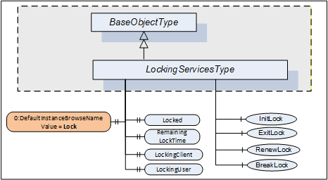
The LockingServicesType provides Methods to manage the lock and Properties with status information. This section describes the common semantic. The lock-owner ObjectTypes will often extend these semantics.
Figure 31 shows the LockingServicesType definition. It is formally defined in Table 65.
| Attribute | Value | ||||
| BrowseName | 1:LockingServicesType | ||||
| IsAbstract | False | ||||
| References | NodeClass | BrowseName | DataType | TypeDefinition | Other |
|---|---|---|---|---|---|
| Subtype of the 0:BaseObjectType defined in OPC 10000-5. | |||||
| 0:HasComponent | Method | 1:InitLock | Defined in 7.5 | M | |
| 0:HasComponent | Method | 1:RenewLock | Defined in 7.7 | M | |
| 0:HasComponent | Method | 1:ExitLock | Defined in 7.6 | M | |
| 0:HasComponent | Method | 1:BreakLock | Defined in 7.8 | M | |
| 0:HasProperty | Variable | 0:DefaultInstanceBrowseName | 0:QualifiedName | 0:PropertyType | |
| 0:HasProperty | Variable | 1:Locked | 0:Boolean | 0:PropertyType | M |
| 0:HasProperty | Variable | 1:LockingClient | 0:String | 0:PropertyType | M |
| 0:HasProperty | Variable | 1:LockingUser | 0:String | 0:PropertyType | M |
| 0:HasProperty | Variable | 1:RemainingLockTime | 0:Duration | 0:PropertyType | M |
| Conformance Units | |||||
|---|---|---|---|---|---|
| DI Locking |
The StatusCode Bad_MethodInvalid shall be returned from the Call Service for Objects where locking is not supported. Bad_UserAccessDenied shall be returned if the Client User does not have the permission to call the Methods.
The DefaultInstanceBrowseName Property - defined in OPC 10000-3 - is used to specify the recommended BrowseName for instances of the LockingServicesType. Its Value is defined in Table 66.
| Source Path | Value |
| 0:DefaultInstanceBrowseName | Lock |
A lock is typically initiated by a Client calling the InitLock Method and removed by calling the ExitLock Method. The lock-owner ObjectTypes can define mechanisms that automatically initiate and remove a lock.
A lock request will be rejected if operations are active that will be prevented by the lock.
The lock is automatically removed if the MaxInactiveLockTime has elapsed (see 7.4). The lock is also removed when the Session ends during inactivity. This is typically the case when the connection to the Client breaks and the Session times out.
The following LockingServices Properties offer lock-status information.
Locked when True indicates that this element has been locked by some Application and that no or just limited access is available for other Applications.
When the lock is initiated by a Client, LockingClient contains the ApplicationUri of the Client as provided in the CreateSession Service call (see OPC 10000-4). Other options to get this information can be specified on the lock-owner ObjectType.
LockingUser contains information to identify the user. When the lock is initiated by a Client it is obtained directly or indirectly from the UserIdentityToken passed by the Client in the ActivateSession Service call (see OPC 10000-4). Other options to get this information can be specified on the lock-owner ObjectType.
RemainingLockTime denotes the remaining time in milliseconds after which the lock will automatically be removed by the Server. This time is based upon MaxInactiveLockTime (see 7.4).
7.3 LockingServices Object
The support of LockingServices for an Object is declared by aggregating an instance of the LockingServicesType as illustrated in Figure 32.
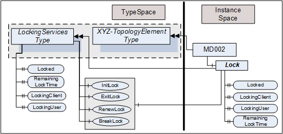
This Object is used as container for the LockingServices Methods and Properties and should have the BrowseName Lock. It shall be referenced using HasComponent or HasAddIn from the lock-owner Object (for example, a Device).
The LockingServicesType and each instance can share the same Methods. All Properties are distinct.
7.4 MaxInactiveLockTime Property
The MaxInactiveLockTime Property shall be added to the ServerCapabilities Object (see OPC 10000-5). It contains a Server-specific period of inactivity in milliseconds after which the Server will revoke the lock.
The Server will initiate a timer based on this time as part of processing the InitLock request and after the last activity caused by the initiator of the lock is finished. Calling the RenewLock Method shall reset the timer.
Inactivity for MaxInactiveLockTime will trigger a timeout. As a result, the Server will release the lock.
The MaxInactiveLockTime Property is formally defined in Table 67.
| References | NodeClass | BrowseName | DataType | TypeDefinition | Other |
| 0:HasProperty | Variable | 1:MaxInactiveLockTime | 0:Duration | 0:PropertyType | M |
7.5 InitLock Method
InitLock restricts access for other UA Applications.
A call of this Method for an element that is already locked will be rejected.
While locked, requests from other Applications to modify the locked element (e.g., writing to Variables, or invoking Methods) should be rejected with Bad_Locked. However, requests to read or navigate will typically work. Servers can choose to implement an exclusive locking where other Applications have no access at all.
The lock is removed when ExitLock is called. It is automatically removed when the MaxInactiveLockTime elapsed (see 7.4).
The signature of this Method is specified below. Table 68 and Table 69 specify the arguments and AddressSpace representation, respectively.
Signature
	InitLock(
	  [in]  0:String       Context,
[out] 0:Int32 InitLockStatus);| Argument | Description |
| Context | A string used to provide context information about the current activity going on in the Client. |
| InitLockStatus | 0 - OK -1 - E_AlreadyLocked - the element is already locked -2 - E_Invalid - the element cannot be locked |
| Attribute | Value | ||||
| BrowseName | 1:InitLock | ||||
| References | NodeClass | BrowseName | DataType | TypeDefinition | Other |
|---|---|---|---|---|---|
| 0:HasProperty | Variable | 0:InputArguments | 0:Argument[] | 0:PropertyType | M |
| 0:HasProperty | Variable | 0:OutputArguments | 0:Argument[] | 0:PropertyType | M |
| Conformance Units | |||||
|---|---|---|---|---|---|
| DI Locking |
7.6 ExitLock Method
ExitLock removes the lock. This Method can only be called from the same Application which initiated the lock.
The signature of this Method is specified below. Table 70 and Table 71 specify the arguments and AddressSpace representation, respectively.
Signature
	ExitLock(
[out] 0:Int32 ExitLockStatus);| Argument | Description |
| ExitLockStatus | 0 - OK -1 - E_NotLocked - the Object is not locked |
| Attribute | Value | ||||
| BrowseName | 1:ExitLock | ||||
| References | NodeClass | BrowseName | DataType | TypeDefinition | Other |
|---|---|---|---|---|---|
| 0:HasProperty | Variable | 0:OutputArguments | 0:Argument[] | 0:PropertyType | M |
| Conformance Units | |||||
|---|---|---|---|---|---|
| DI Locking |
7.7 RenewLock Method
The lock timer is automatically renewed whenever the initiator of the lock issues a request for the locked element or while Nodes of the locked element are subscribed to. RenewLock is used to reset the lock timer to the value of the MaxInactiveLockTime Property and prevent the Server from automatically removing the lock. This Method can only be called from the same Application which initiated the lock.
The signature of this Method is specified below. Table 72 and Table 73 specify the arguments and AddressSpace representation, respectively.
Signature
	RenewLock(
[out] 0:Int32 RenewLockStatus);| Argument | Description |
| RenewLockStatus | 0 - OK -1 - E_NotLocked - the Object is not locked |
| Attribute | Value | |||||
| BrowseName | 1:RenewLock | |||||
| References | NodeClass | BrowseName | DataType | TypeDefinition | Other | |
|---|---|---|---|---|---|---|
| 0:HasProperty | Variable | 0:OutputArguments | 0:Argument[] | 0:PropertyType | M | |
| Conformance Units | |||||
|---|---|---|---|---|---|
| DI Locking |
7.8 BreakLock Method
BreakLock allows a Client (with sufficiently high user rights) to break the lock. This Method will typically be available only to users with administrator privileges. BreakLock should be used with care as the locked element can be in an inconsistent state.
The signature of this Method is specified below. Table 74 and Table 75 specify the arguments and AddressSpace representation, respectively.
Signature
	BreakLock(
[out] 0:Int32 BreakLockStatus);| Argument | Description |
| BreakLockStatus | 0 - OK -1 - E_NotLocked - the Object is not locked |
| Attribute | Value | ||||
| BrowseName | 1:BreakLock | ||||
| References | NodeClass | BrowseName | DataType | TypeDefinition | Other |
|---|---|---|---|---|---|
| 0:HasProperty | Variable | 0:OutputArguments | 0:Argument[] | 0:PropertyType | M |
| Conformance Units | |||||
|---|---|---|---|---|---|
| DI Locking |