Clause 6 introduces References, the ProtocolType, and basic TopologyElementTypes needed to create a communication topology. The types for this model are illustrated in Figure 19.
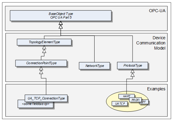
Figure 19 – Device communication model overview
A ProtocolType ObjectType represents a specific communication protocol (e.g. FieldBus) implemented by a certain TopologyElement. Examples are shown in Figure 21.
The ConnectionPointType represents the logical interface of a Device to a Network.
A Network is the logical representation of wired and wireless technologies.
Figure 20 provides an overall example.
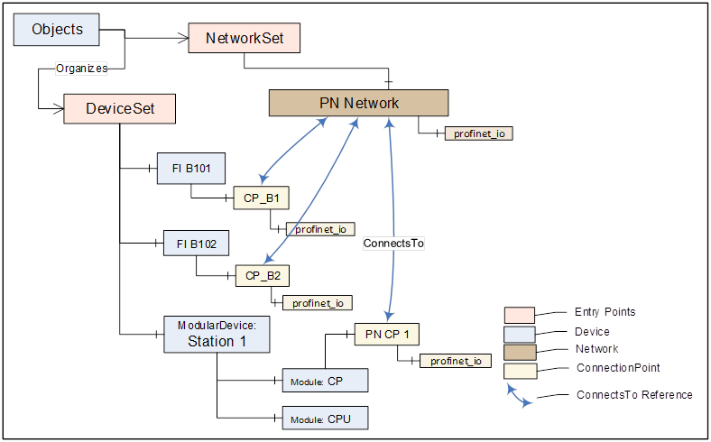
Figure 20 – Example of a communication topology
The ProtocolType ObjectType and its subtypes are used to specify a specific communication (e.g. FieldBus) protocol that is supported by a Device (respectively by its ConnectionPoint) or Network. The BrowseName of each instance of a ProtocolType shall define the Communication Profile (see Figure 21).
Figure 21 shows the ProtocolType including some specific types and instances that represent Communication Profiles of that type. It is formally defined in Table 36.
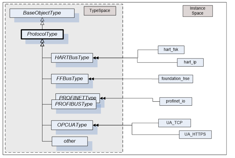
Figure 21 – Example of a ProtocolType hierarchy with instancesthat represent specific communication profiles
Table 36 – ProtocolType definition
|
Attribute |
Value |
||||
|
BrowseName |
ProtocolType |
||||
|
IsAbstract |
False |
||||
|
References |
NodeClass |
BrowseName |
DataType |
TypeDefinition |
ModellingRule |
|
Subtype of the BaseObjectType defined in OPC 10000-5 |
|||||
|
|
|
|
|
|
|
A Network is the logical representation of wired and wireless technologies and represents the communication means for Devices that are connected to it. A Network instance is qualified by its Communication Profile components.
Figure 22 shows the type hierarchy and the NetworkType components. It is formally defined in Table 37.
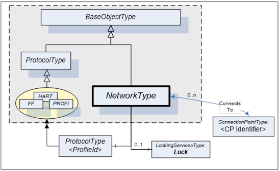
Table 37 – NetworkType definition
|
Attribute |
Value |
||||
|
BrowseName |
NetworkType |
||||
|
IsAbstract |
False |
||||
|
References |
NodeClass |
BrowseName |
DataType |
TypeDefinition |
ModellingRule |
|
Subtype of the BaseObjectType defined in OPC 10000-5. |
|||||
|
HasComponent |
Object |
<ProfileIdentifier> |
|
ProtocolType |
MandatoryPlaceholder |
|
ConnectsTo |
Object |
<CPIdentifier> |
|
ConnectionPointType |
OptionalPlaceholder |
|
HasComponent |
Object |
Lock |
|
LockingServicesType |
Optional |
The <ProfileIdentifier> specifies the Protocol and Communication Profile that this Network is used for.
<CPIdentifier> (referenced by a ConnectsTo Reference) references the ConnectionPoint(s) that have been configured for this Network. All ConnectionPoints shall adhere to the same Protocol as the Network. See also Figure 25 for a usage example. They represent the protocol-specific access points for the connected Devices.
In addition, Networks may also support LockingServices (defined in 8.3).
This ObjectType represents the logical interface of a Device to a Network. A specific subtype shall be defined for each protocol. Figure 23 shows the ConnectionPointType including some specific types.
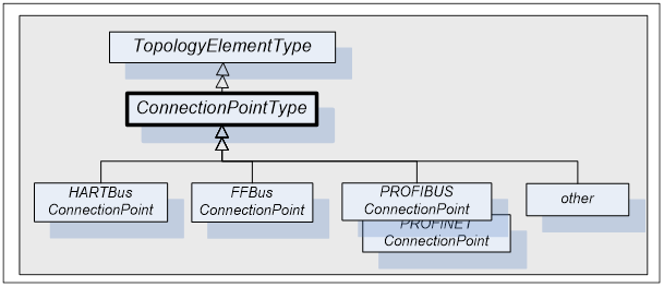
Figure 23 – Example of ConnectionPointType hierarchy
A Device can have more than one such interface to the same or to different Networks. Different interfaces usually exist for different protocols. Figure 24 shows the ConnectionPointType components. It is formally defined in Table 38.
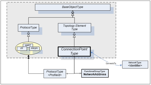
Figure 24 – ConnectionPointType
Table 38 – ConnectionPointType definition
|
Attribute |
Value |
||||
|
BrowseName |
ConnectionPointType |
||||
|
IsAbstract |
True |
||||
|
References |
NodeClass |
BrowseName |
DataType |
TypeDefinition |
ModellingRule |
|
Subtype of the TopologyElementType defined in 5.2. |
|||||
|
HasComponent |
Object |
NetworkAddress |
|
FunctionalGroupType |
Mandatory |
|
HasComponent |
Object |
<ProfileIdentifier> |
|
ProtocolType |
MandatoryPlaceholder |
|
ConnectsTo |
Object |
<NetworkIdentifier> |
|
NetworkType |
OptionalPlaceholder |
ConnectionPoints are components of a Device, represented by a subtype of ComponentType. To allow navigation from a Network to the connected Devices, the ConnectionPoints shall have the inverse Reference (ComponentOf) to the Device.
ConnectionPoints have Properties and other components that they inherit from the TopologyElementType.
The NetworkAddress FunctionalGroup includes all Parameters needed to specify the protocol-specific address information of the connected Device. These Parameters may be components of the NetworkAddress FunctionalGroup, of the ParameterSet, or another Object.
<ProfileIdentifier> identifies the Communication Profile that this ConnectionPoint supports. ProtocolType and Communication Profile are defined in 6.2. It implies that this ConnectionPoint can be used to connect Networks and Devices of the same Communication Profile.
ConnectionPoints are between a Network and a Device. The location in the topology is configured by means of the ConnectsTo ReferenceType. Figure 25 illustrates some usage models.
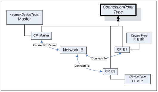
Figure 25 – ConnectionPoint usage
The ConnectsTo ReferenceType is a concrete ReferenceType used to indicate that source and target Node have a topological connection. It is both hierarchical and symmetric, because this is natural for this Reference. The ConnectsTo Reference exists between a Network and the connected Devices (or their ConnectionPoint, respectively). Browsing a Network returns the connected Devices; browsing from a Device, one can follow the ConnectsTo Reference from the Device’s ConnectionPoint to the Network.
The ConnectsToParent ReferenceType is a concrete ReferenceType used to define the parent (i.e. the communication Device) of a Network. It is a subtype of The ConnectsTo ReferenceType.
The two ReferenceTypes are illustrated in Figure 26.
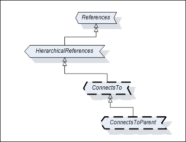
Figure 26 – Type Hierarchy for ConnectsTo and ConnectsToParent References
The representation in the AddressSpace is specified in Table 39 and Table 40.
Table 39 – ConnectsTo ReferenceType
|
Attributes |
Value |
||
|
BrowseName |
ConnectsTo |
||
|
Symmetric |
True |
||
|
IsAbstract |
False |
||
|
References |
NodeClass |
BrowseName |
Comment |
|
Subtype of HierarchicalReferences ReferenceType defined in OPC 10000-5. |
|||
Table 40 – ConnectsToParent ReferenceType
|
Attributes |
Value |
||
|
BrowseName |
ConnectsToParent |
||
|
Symmetric |
True |
||
|
IsAbstract |
False |
||
|
References |
NodeClass |
BrowseName |
Comment |
|
Subtype of ConnectsTo ReferenceType |
|||
Figure 27 illustrates how this Reference can be used to express topological relationships and parental relationships. In this example two Devices are connected; the module DPcomm is the communication Device for the Network.
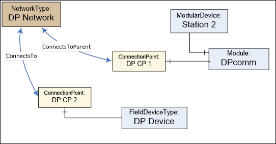
Figure 27 – Example with ConnectsTo and ConnectsToParent References
All Networks shall be components of the NetworkSet Object.
The NetworkSet Node is formally defined in Table 41.
Table 41 – NetworkSet definition
|
Attribute |
Value |
||
|
BrowseName |
NetworkSet |
||
|
References |
NodeClass |
BrowseName |
TypeDefinition |
|
OrganizedBy by the Objects Folder defined in OPC 10000-5 |
|||
|
HasTypeDefinition |
ObjectType |
BaseObjectType |
|