The following examples show the Event flow for typical Alarm situations. The tables list the value of state Variables for each Event Notification.
This example is for Servers that do not support previous states and therefore do not create and maintain Branches of a single Condition.
Figure B.1 shows an Alarm as it becomes active and then inactive and also the acknowledgement and confirmation cycles. Table B.1 lists the values of the state Variables. All Events are coming from the same Condition instance and therefore have the same ConditionId.
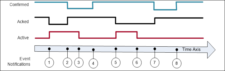
Figure B.1 – Single state example
Table B.1 – Example of a Condition that only keeps the latest state
|
EventId |
BranchId |
Active |
Acked |
Confirmed |
Retain |
Description |
|
-*) |
NULL |
False |
True |
True |
False |
Initial state of Condition. |
|
1 |
NULL |
True |
False |
True |
True |
Alarm goes active. |
|
2 |
NULL |
True |
True |
False |
True |
Condition acknowledged Confirm required |
|
3 |
NULL |
False |
True |
False |
True |
Alarm goes inactive. |
|
4 |
NULL |
False |
True |
True |
False |
Condition confirmed |
|
5 |
NULL |
True |
False |
True |
True |
Alarm goes active. |
|
6 |
NULL |
False |
False |
True |
True |
Alarm goes inactive. |
|
7 |
NULL |
False |
True |
False |
True |
Condition acknowledged, Confirm required. |
|
8 |
NULL |
False |
True |
True |
False |
Condition confirmed. |
|
*) The first row is included to illustrate the initial state of the Condition. This state will not be reported by an Event. |
||||||
This example is for Servers that are able to maintain previous states of a Condition and therefore create and maintain Branches of a single Condition.
Figure B.2 illustrates the use of branches by a Server requiring acknowledgement of all transitions into Active state, not just the most recent transition. In this example no acknowledgement is required on a transition into an inactive state. Table B.2 lists the values of the state Variables. All Events are coming from the same Condition instance and have therefore the same ConditionId.
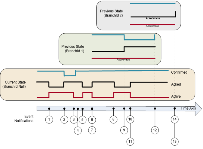
Figure B.2 – Previous state example
Table B.2 – Example of a Condition that maintains previous states via branches
|
EventId |
BranchId |
Active |
Acked |
Confirmed |
Retain |
Description |
|
a) |
NULL |
False |
True |
True |
False |
Initial state of Condition. |
|
1 |
NULL |
True |
False |
True |
True |
Alarm goes active. |
|
2 |
NULL |
True |
True |
True |
True |
Condition acknowledged requires Confirm |
|
3 |
NULL |
False |
True |
False |
True |
Alarm goes inactive. |
|
4 |
NULL |
False |
True |
True |
False |
Confirmed |
|
5 |
NULL |
True |
False |
True |
True |
Alarm goes active. |
|
6 |
NULL |
False |
True |
True |
True |
Alarm goes inactive. |
|
7 |
1 |
True |
False |
True |
True b) |
Prior state needs acknowledgment. Branch #1 created. |
|
8 |
NULL |
True |
False |
True |
True |
Alarm goes active again. |
|
9 |
1 |
True |
True |
False |
True |
Prior state acknowledged, Confirm required. |
|
10 |
NULL |
False |
True |
True |
True b) |
Alarm goes inactive again. |
|
11 |
2 |
True |
False |
True |
True |
Prior state needs acknowledgment. Branch #2 created. |
|
12 |
1 |
True |
True |
True |
False |
Prior state confirmed. Branch #1 deleted. |
|
13 |
2 |
True |
True |
True |
False |
Prior state acknowledged, Auto Confirmed by system Branch #2 deleted. c) |
|
14 |
NULL |
False |
True |
True |
False |
No longer of interest. |
|
a) The first row is included to illustrate the initial state of the Condition. This state will not be reported by an Event. Notes on specific situations shown with this example: If the current state of the Condition is acknowledged then the Acked flag is set and the new state is reported (Event #2). If the Condition state changes before it can be acknowledged (Event #6) then a branch state is reported (Event #7). Timestamps for the Events #6 and #7 is identical. The branch state can be updated several times (Events #9) before it is cleared (Event #12). A single Condition can have many branch states active (Events #11) b) It is recommended as in this table to leave Retain=True as long as there exist previous states (branches). c) The system Auto confirms this event, since a confirmation is that the operator has taken some action. The confirmation of the previous state (line 12) indicates that the operator has taken an action and this transition does not require a separate confirmation. |
||||||
This example adds additional fields to the model illustrated in B.1.2. This example does not use acknowledge or confirm – it assumes that the alarm is automatically acknowledged (and does not support confirm). It does add OutOfServiceState and SuppressedState.
Figure B.3 shows an Alarm as it becomes active, is suppressed or is placed out of service and then inactive. Table B.3 lists the values of the state Variables. All Events are coming from the same Condition instance and therefore have the same ConditionId. The Client subscription includes an event filter that excludes suppressed or out of service conditions (i.e. SuppressedState = True or OutOfServiceState = True). The events shown in green are delivered to the Client. The Retain column indicates the global value of the Retain flag. The “Retain sent” column indicates the overridden value sent in a notification if SupportsFilteredRetain is True. If SupportsFilteredRetain is False the value from the Retain column is sent.
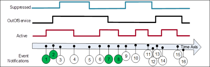
Figure B.3 – SuppressedState and OutOfServiceState example
Table B.3 – Example of a Condition that is Suppressed / OutOfService
|
EventId |
Active |
Suppressed State |
OutOf Service State |
Retain |
Retain sent |
Event Deliver with Filter |
Description |
|
-*) |
False |
False |
False |
False |
False |
- |
Initial state of Condition. |
|
1 |
True |
False |
False |
True |
True |
Yes |
Alarm goes active. |
|
2 |
True |
False |
True |
True |
False |
Yes |
Placed OutOfService |
|
3 |
True |
True |
True |
True |
False |
No |
Alarm Suppressed; No event since OutOfService |
|
4 |
False |
True |
True |
False |
False |
No |
Alarm goes inactive; No event since OutOfService |
|
5 |
False |
False |
True |
False |
False |
No |
Alarm not Suppressed; No event since not active |
|
6 |
True |
False |
True |
True |
False |
No |
Alarm goes active; No event since OutOfService |
|
7 |
True |
False |
False |
True |
True |
Yes |
Alarm no longer OutOfService; Event generated |
|
8 |
False |
False |
False |
False |
False |
Yes |
Alarm goes inactive |
|
9 |
False |
True |
False |
False |
False |
No |
Alarm Suppressed; No event since not active |
|
10 |
True |
True |
False |
True |
False |
No |
Alarm goes active; No event since Suppressed |
|
11 |
False |
True |
False |
False |
False |
No |
Alarm goes inactive; No event since Suppressed |
|
12 |
False |
False |
False |
False |
False |
No |
Alarm no longer Suppressed |
|
13 |
False |
False |
True |
False |
False |
No |
Placed OutOfService |
|
14 |
True |
False |
True |
True |
False |
No |
Alarm goes active; No event since OutOfService |
|
15 |
False |
False |
True |
False |
False |
No |
Alarm goes inactive; No event since OutOfService |
|
16 |
False |
False |
False |
False |
False |
No |
Alarm no longer OutOfService |
This behaviour occurs when the implementation supports SupportsFilteredRetain flag subscription.
This example illustrates how on-delay, off-delay and alarm dead bands can be used to reduce the number of alarms that are generated / reported (see 5.8). It also illustrates how ReAlarmTime is used to bring an alarm back up to an active state (see Figure B.4).
Some process values may have sudden jumps that are very brief and do not constitute an alarm. For example, a motor on start draws a large current, but quickly come back down. This is a normal motor current load, and should not be alarmed, but a sustained current load is a problem and should be alarmed, by configuring a OnDelay time, the momentary spike will not generate an alarm, since the value has to be above the alarm threshold for the duration of OnDelay.
An AlarmDeadband is used to keep a noise signal from generating multiple Alarm activations a signal once it crosses an alarm limit will not return to norm unless it drops below the limit by the amount of the deadband specified. In the example the process value is jumping up and down around the limit, but the alarm just remains in the same active or acknowledged state. The Alarm can have a deadband for each limit (High vs HighHigh) and these deadbands can be different.
The OffDelay can also be used, much as the OnDelay, except it will keep a Value in alarm even if it drops below a limit, but only very briefly. Again, this setting is used to limit the number of alarms that occur in a system.
The ReAlarmTime is used to ensure that actions are taken to correct the issue that generated an alarm. Some alarms are configured to generate a new alarm if they have been in an active state for the ReAlarmTime period. The Alarm, goes back to an Unacknowledged state, as if it had just occurred.
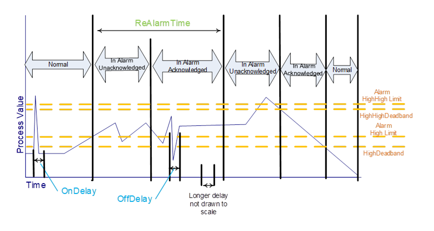
Figure B.4 - Alarm example - On Delay, Off Delay, ReAlarmTime