Alarms are specializations of AcknowledgeableConditions that add the concepts of an Active state and other states like Shelving state and Suppressed state to a Condition. The state model is illustrated in Figure 55. The complete model with all states is defined in 5.8.
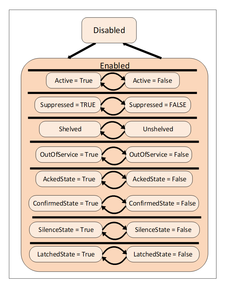
Figure 55 – Alarm state machine model
An Alarm in the Active state indicates that the situation the Condition is representing currently exists. When an Alarm is an inactive state it is representing a situation that has returned to a normal state.
Some Alarm subtypes introduce sub-states of the Active state. For example, an Alarm representing a temperature may provide a high level state as well as a critically high state (see following Clause).
The shelving state can be set by an Operator via OPC UA Methods. The suppressed state is set internally by the Server due to system specific reasons. Alarm systems typically implement the suppress, out of service and shelve features to help keep Operators from being overwhelmed during Alarm “storms” by limiting the number of Alarms an Operator sees on a current Alarm display. This is accomplished by setting the SuppressedOrShelved flag on second order dependent Alarms and/or Alarms of less severity, leading the Operator to concentrate on the most critical issues.
The LatchedState is a state that is added to any alarm that requires additional processing, once it goes active it does not clear until it is explicitly reset, even if the value that triggered the alarm returns to normal. This can be an alarm that requires a physical inspection once it has occurred to ensure it is no longer in alarm, or a series of tests that might be required to ensure the alarm is no longer active or some other actions. Any AlarmType can become a latched alarm by the addition of this optional sub-state.
The shelved, out of service and suppressed states differ from the Disabled state in that Alarms are still fully functional and can be included in Subscription Notifications to a Client. A disabled Alarm is not processed in any manner, and is not supported as part of the active Alarm model defined in ISA 18.2.
Alarms follow a typical timeline that is illustrated in Figure 66. They have a number of delay times associated with them and a number of states that they might occupy. The goal of an alarming system is to inform Operators about conditions in a timely manner and allow the Operator to take some action before some consequences occur. The consequences may be economic (product is not usable and is discard), may be physical (tank overflows), may safety (fire or explosion could occur) or any of a number of other possibilities. Typically, if no action is taken related to an alarm for some period of time the process will cross some threshold at which point consequences will start to occur. The OPC UA Alarm model describes these states, delays and actions.
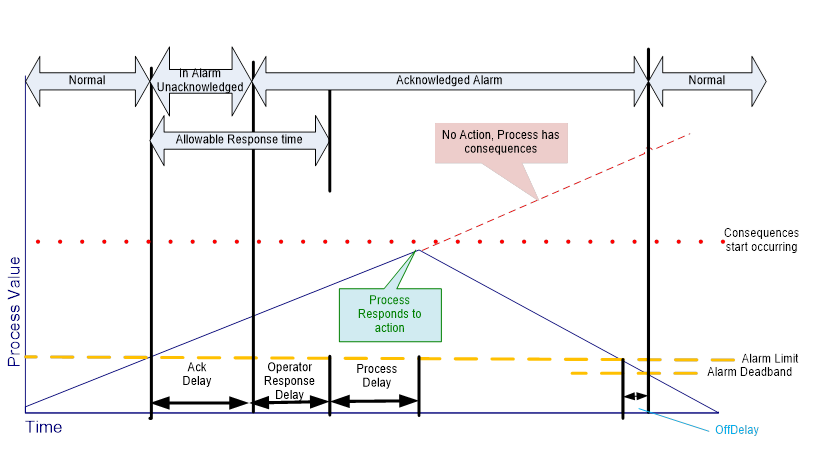
Figure 66 – Typical Alarm Timeline example