Nodes and their References to each other are illustrated using figures. Figure 1 illustrates the conventions used in these figures.
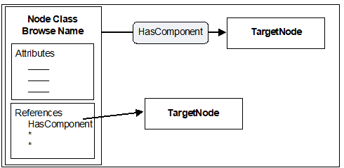
Figure 1 – AddressSpace Node diagrams
In these figures, rectangles represent Nodes. Node rectangles may be titled with one or two lines of text. When two lines are used, the first text line in the rectangle identifies the NodeClass and the second line contains the BrowseName. When one line is used, it contains the BrowseName.
Node rectangles may contain boxes used to define their Attributes and References. Specific names in these boxes identify specific Attributes and References.
Shaded rectangles with rounded corners and with arrows passing through them represent References. The arrow that passes through them begins at the SourceNode and points to the TargetNode. References may also be shown by drawing an arrow that starts at the Reference name in the “References” box and ends at the TargetNode.