
5 Base Network Model
5.1 Overview
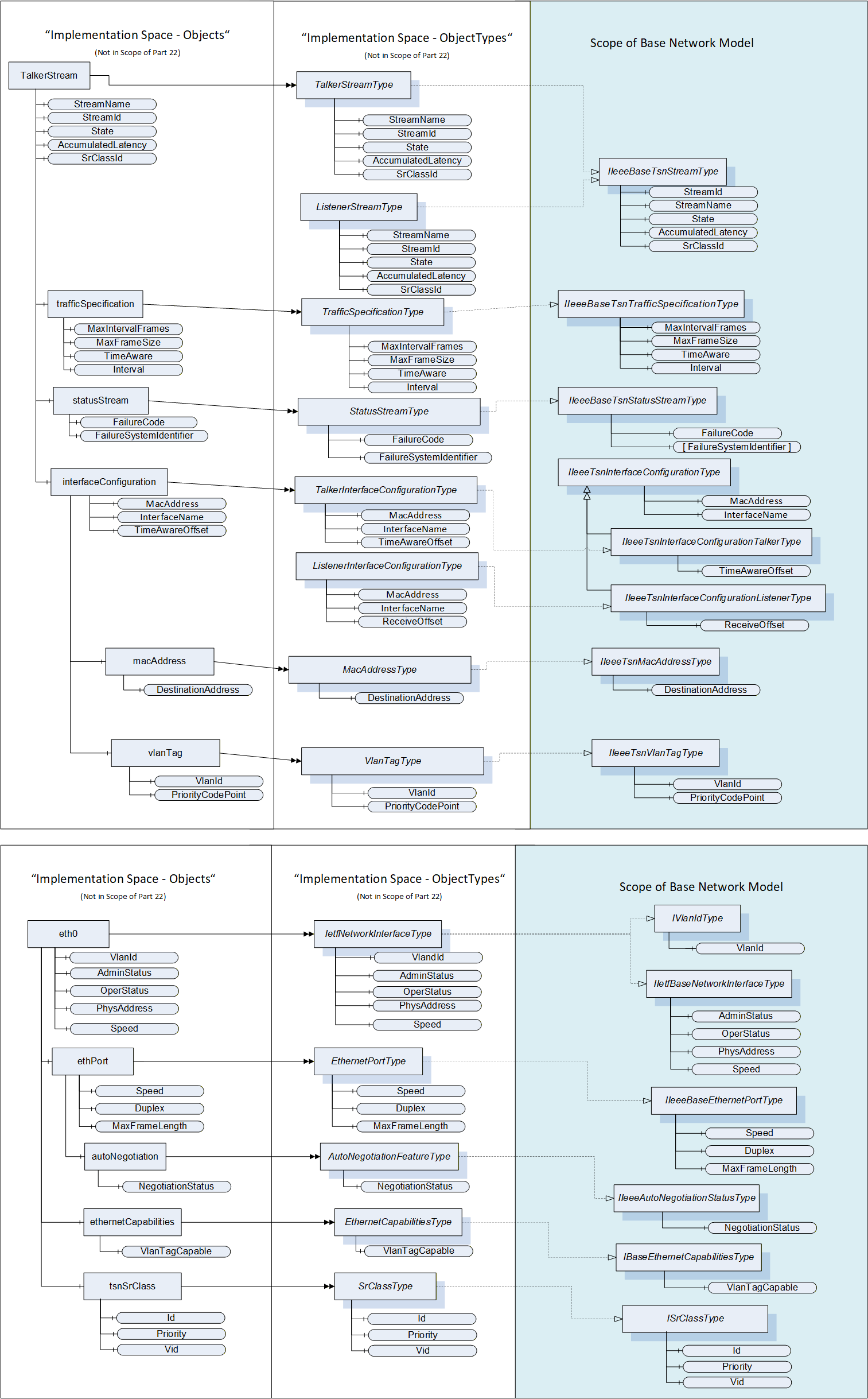
The Base Network Model defined in this document is shown in Figure 2.
5.2 OPC UA InterfaceTypes
5.2.1 IIetfBaseNetworkInterfaceType Interface
This OPC UA Interface defines the basis of an IETF network interface. The IIetfBaseNetworkInterfaceType is formally defined in Table 1.
| Attribute | Value | ||||
| BrowseName | IIetfBaseNetworkInterfaceType | ||||
| IsAbstract | True | ||||
| References | NodeClass | BrowseName | DataType | TypeDefinition | ModellingRule |
|---|---|---|---|---|---|
| Subtype of the BaseInterfaceType defined in OPC 10000-5 | |||||
| HasComponent | Variable | AdminStatus | InterfaceAdminStatus | BaseDataVariableType | Mandatory |
| HasComponent | Variable | OperStatus | InterfaceOperStatus | BaseDataVariableType | Mandatory |
| HasComponent | Variable | PhysAddress | String | BaseDataVariableType | Optional |
| HasComponent | Variable | Speed | UInt64 | AnalogUnitType | Mandatory |
| Conformance Units | |||||
|---|---|---|---|---|---|
| BNM Ethernet Base Info |
AdminStatus of DataType InterfaceAdminStatus specifies the desired state of the network interface. This Variable has the same read semantics as ifAdminStatus (ifAdminStatus is defined in IETF RFC 2863). The InterfaceAdminStatus Enumeration is defined in 5.3.1.2.
OperStatus of DataType InterfaceOperStatus specifies the current operational state of the network interface. This Variable has the same semantics as ifOperStatus (ifOperStatus is defined in IETF RFC 2863). The InterfaceOperStatus Enumeration is defined in 5.3.1.3.
PhysAddress of DataType String specifies the network interface's address at its protocol sub-layer. For example, for an 802.x network interface, this parameter normally contains a Media Access Control (MAC) address. The network interface's media-specific modules must define the bit and byte ordering and the format of the value of this object. For network interfaces that do not have such an address (e.g., a serial line), this node is not present (ifPhysAddress is defined in IETF RFC 2863).
Speed of DataType UInt64 specifies an estimate of the network interface's current bandwidth in bits per second. For network interfaces that do not vary in bandwidth or for those where no accurate estimation can be made, this value should contain the nominal bandwidth (ifSpeed and ifHighSpeed are defined in IETF RFC 2863).
The component Variables of the IIetfBaseNetworkInterfaceType have the Attribute values defined in Table 2.
| Source Path | Value Attribute | Description Attribute |
NamespaceUri: http://www.opcfoundation.org/UA/units/un/cefact UnitId: 4337968 | - |
5.2.2 IIeeeBaseEthernetPortType Interface
This OPC UA Interface defines capabilities of an Ethernet-based port. The IIeeeBaseEthernetPortType is formally defined in Table 3.
| Attribute | Value | ||||
| BrowseName | IIeeeBaseEthernetPortType | ||||
| IsAbstract | True | ||||
| References | NodeClass | BrowseName | DataType | TypeDefinition | Modelling Rule |
|---|---|---|---|---|---|
| Subtype of the BaseInterfaceType defined in OPC 10000-5 | |||||
| HasComponent | Variable | Speed | UInt64 | AnalogUnitType | Mandatory |
| HasComponent | Variable | Duplex | Duplex | BaseDataVariableType | Mandatory |
| HasComponent | Variable | MaxFrameLength | UInt16 | BaseDataVariableType | Mandatory |
| Conformance Units | |||||
|---|---|---|---|---|---|
| BNM Ethernet Base Info |
Speed of DataType UInt64 specifies the configured, negotiated, or actual speed of an Ethernet port in entities of 1 Mb/s (data rate). The default value is implementation-dependent (Ethernet ports are defined in IEEE 802.3-2022).
Duplex of DataType Duplex represents the configured, negotiated, or actual duplex mode of an Ethernet port (aDuplexStatus is defined in IEEE 802.3-2022, clause 30.3.1.1.32, aDuplexStatus). The Duplex DataType is defined in 5.3.1.1.
MaxFrameLength of DataType UInt16 indicates the MAC frame length (including FCS bytes) at which frames are dropped for being too long (aMaxFrameLength is defined in IEEE 802.3-2022, clause 30.3.1.1.37, aMaxFrameLength).
The component Variables of the IIeeeBaseEthernetPortType have the Attribute values defined in Table 4.
| Source Path | Value Attribute | Description Attribute |
NamespaceUri: http://www.opcfoundation.org/UA/units/un/cefact UnitId: 4534832 | - |
5.2.3 IIeeeAutoNegotiationStatusType Interface
This OPC UA Interface defines the auto negotiation status of an Ethernet-based port. The IIeeeAutoNegotiationStatusType is formally defined in Table 5.
| Attribute | Value | ||||
| BrowseName | IIeeeAutoNegotiationStatusType | ||||
| IsAbstract | True | ||||
| References | NodeClass | BrowseName | DataType | TypeDefinition | Modelling Rule |
|---|---|---|---|---|---|
| Subtype of the BaseInterfaceType defined in OPC 10000-5 | |||||
| HasComponent | Variable | NegotiationStatus | NegotiationStatus | BaseDataVariableType | Mandatory |
| Conformance Units | |||||
|---|---|---|---|---|---|
| BNM AutoNeg |
NegotiationStatus of DataType NegotiationStatus specifies the status of the auto-negotiation protocol (aAutoNegAutoConfig is defined in IEEE 802.3-2022, clause 30.6.1.1.4, aAutoNegAutoConfig). The NegotiationStatus DataType is defined in 5.3.1.4.
5.2.4 IBaseEthernetCapabilitiesType Interface
This OPC UA Interface defines if an Ethernet-based port is VLAN Tag capable. The IBaseEthernetCapabilitiesType is formally defined in Table 6.
| Attribute | Value | ||||
| BrowseName | IBaseEthernetCapabilitiesType | ||||
| IsAbstract | True | ||||
| References | NodeClass | BrowseName | DataType | TypeDefinition | Modelling Rule |
|---|---|---|---|---|---|
| Subtype of the BaseInterfaceType defined in OPC 10000-5 | |||||
| HasComponent | Variable | VlanTagCapable | Boolean | BaseDataVariableType | Mandatory |
| Conformance Units | |||||
|---|---|---|---|---|---|
| BNM VLAN Capabilities |
When VlanTagCapable is true, the network interface supports the ability to tag/untag frames using a Customer VLAN Tag (C-TAG of clause 9) provided by the network (VLAN Tags are defined in IEEE 802.1Qcc-2018, clause 46.2.3.7.1).
5.2.5 IVlanIdType Interface
This OPC UA Interface specifies a VLAN Id to be associated with a network interface. The IVlanIdType is formally defined in Table 7.
| Attribute | Value | ||||
| BrowseName | IVlanIdType | ||||
| IsAbstract | True | ||||
| References | NodeClass | BrowseName | DataType | TypeDefinition | Modelling Rule |
| Subtype of the BaseInterfaceType defined in OPC 10000-5 | |||||
| HasComponent | Variable | VlanId | UInt16 | BaseDataVariableType | Mandatory |
| Conformance Units | |||||
|---|---|---|---|---|---|
| BNM IETF Interface Vlan Info |
VlanId is an UInt16 and contains the Customer VLAN Tag (IEEE 802.1Q-2018 C-TAG of clause 9) that frames injected at this network interface will be tagged with (VlanId is defined in IEEE 802.1Qcc-2018 clause 46.2.3.7.1).
5.2.6 ISrClassType Interface
This OPC UA Interface defines the content of an SrClass. The ISrClassType is formally defined in Table 8.
| Attribute | Value | ||||
| BrowseName | ISrClassType | ||||
| IsAbstract | True | ||||
| References | NodeClass | BrowseName | DataType | TypeDefinition | Modelling Rule |
|---|---|---|---|---|---|
| Subtype of the BaseInterfaceType defined in OPC 10000-5 | |||||
| HasComponent | Variable | Id | Byte | BaseDataVariableType | Mandatory |
| HasComponent | Variable | Priority | Byte | BaseDataVariableType | Mandatory |
| HasComponent | Variable | Vid | UInt16 | BaseDataVariableType | Mandatory |
| Conformance Units | |||||
|---|---|---|---|---|---|
| BNM TSN Base Info |
Id is a Byte and specifies the SRclassID in a numeric representation of the SR classes which is supported by a particular Bridge Port (SRclassID is defined in IEEE 802.1Q-2018, clause 35.2.2.9.2, SRclassID). Only Values between 0 and 7 shall be used.
Priority is a Byte and holds the Data Frame Priority (item a in IEEE 802.1Q-2018 clause 35.2.2.8.5) value that will be used for streams that belong to the associated SR class. (SRclassPriority is defined in IEEE 802.1Q-2018, clause 35.2.2.9.3, SRclassPriority). Only Values between 0 and 7 shall be used.
Vid is an UInt16 and contains the SR_PVID (item i) in IEEE 802.1Q-2018 clause 35.2.1.4) that the associated streams will be tagged with by the Talker (SRclassVID is defined in IEEE 802.1Q-2018, clause 35.2.2.9.4, SRclassVID).
5.2.7 IIeeeBaseTsnStreamType Interface
The IIeeeBaseTsnStreamType contains Variables which are common for both TSN talkers and TSN listeners. They represent the configuration properties and diagnostic values like reservation status and failure codes of a TSN stream. The IIeeeBaseTsnStreamType is formally defined Table 9.
| Attribute | Value | ||||
| BrowseName | IIeeeBaseTsnStreamType | ||||
| IsAbstract | True | ||||
| References | NodeClass | BrowseName | DataType | TypeDefinition | ModellingRule |
|---|---|---|---|---|---|
| Subtype of the BaseInterfaceType defined in OPC 10000-5 | |||||
| HasComponent | Variable | StreamId | Byte[8] | BaseDataVariableType | Mandatory |
| HasComponent | Variable | StreamName | String | BaseDataVariableType | Mandatory |
| HasComponent | Variable | State | TsnStreamState | BaseDataVariableType | Mandatory |
| HasComponent | Variable | AccumulatedLatency | UInt32 | BaseDataVariableType | Optional |
| HasComponent | Variable | SrClassId | Byte | BaseDataVariableType | Optional |
| Conformance Units | |||||
|---|---|---|---|---|---|
| BNM TSN Base Info |
StreamId is an array of 8 Bytes defined according to the StreamID in IEEE 802.1Qcc-2018 clause 35.2.2.8.2. The StreamId shall be unique in the scope of the related TSN Network. The mapping between the StreamId Byte array and the IEEE octet string StreamID is as follows: Entry[n] of StreamId is mapped to octet[n] of StreamID. The StreamId shall be provided in the TSN stream Objects for diagnostic reasons.
StreamName is a String identifying the related stream in the network. The format of the String is application specific. The uniqueness of the StreamName inside the network segment shall be guaranteed by the application. If multiple applications use the network segment, they need to agree on a naming scheme.
State represents the current state of the TSN configuration process of a TSN stream. The TsnStreamState Enumeration is defined in 5.3.1.6.
AccumulatedLatency of DataType UInt32 is the maximum worst case propagation delay in nanoseconds calculated and guaranteed by the TSN Control Layer for this Listener. Once the stream reservation has succeeded the AccumulatedLatency is not expected to increase during the lifecycle of the TSN Stream (AccumulatedLatency is defined in IEEE 802.1Q-2018 clause 35.2.2.8.6).
SrClassId of DataType Byte contains the Stream Reservation Class that is used for this stream (as defined in IEEE 802.1Qcc-2018 clause 35.2.2.9.2).
5.2.8 IIeeeBaseTsnTrafficSpecificationType Interface
This OPC UA Interface is used to represent the traffic specification of a TSN stream. The IIeeeBaseTsnTrafficSpecificationType is formally defined in Table 10.
| Attribute | Value | ||||
| BrowseName | IIeeeBaseTsnTrafficSpecificationType | ||||
| IsAbstract | True | ||||
| References | NodeClass | BrowseName | DataType | TypeDefinition | Modelling Rule |
|---|---|---|---|---|---|
| Subtype of the BaseInterfaceType defined in OPC 10000-5 | |||||
| HasComponent | Variable | MaxIntervalFrames | UInt16 | BaseDataVariableType | Mandatory |
| HasComponent | Variable | MaxFrameSize | UInt32 | BaseDataVariableType | Mandatory |
| HasComponent | Variable | Interval | UnsignedRationalNumber | BaseDataVariableType | Mandatory |
| Conformance Units | |||||
|---|---|---|---|---|---|
| BNM TSN Config |
The MaxFrameSize of DataType UInt16 specifies the maximum size frame that will be sent by a Talker for this Stream (as defined in IEEE 802.1Q-2018 clause 35.2.2.8.4a).
The MaxIntervalFrames of DataType UInt16 Variable specifies the maximum number of frames that will be sent during an Interval. (as defined in IEEE 802.1Q-2018, clause 35.2.2.8.4b, “MaxIntervalFrames” or IEEE 802.1Qcc-2018, clause 35.2.2.10.6, “MaxFramesPerInterval”)
Interval of DataType UnsignedRationalNumber defines the time period of the TSN Stream in nanoseconds. In that interval a specified number of frames (MaxIntervalFrames) with a maximum payload size per frame (MaxFrameSize) and a maximum total number of bytes (MaxBytesPerInterval) will be transmitted. The Interval therefore shall either represent the “class measurement interval” as used for AVB based Streams (as defined in IEEE 802.1Q-2018 clause 35 or the “Interval” parameter used in the TrafficSpecification group in IEEE 802.1Qcc-2018 clause 46.2.3.5.1).
5.2.9 IIeeeBaseTsnStatusStreamType Interface
This OPC UA Interface is used to represent the status of a TSN stream. The IIeeeBaseTsnStatusStreamType is formally defined in Table 11.
| Attribute | Value | ||||
| BrowseName | IIeeeBaseTsnStatusStreamType | ||||
| IsAbstract | True | ||||
| References | NodeClass | BrowseName | DataType | TypeDefinition | ModellingRule |
|---|---|---|---|---|---|
| Subtype of the BaseInterfaceType defined in OPC 10000-5 | |||||
| HasComponent | Variable | TalkerStatus | TsnTalkerStatus | BaseDataVariableType | Optional |
| HasComponent | Variable | ListenerStatus | TsnListenerStatus | BaseDataVariableType | Optional |
| HasComponent | Variable | FailureCode | TsnFailureCode | BaseDataVariableType | Mandatory |
| HasComponent | Variable | FailureSystemIdentifier | Byte[][8] | BaseDataVariableType | Mandatory |
| Conformance Units | |||||
|---|---|---|---|---|---|
| BNM TSN Base Info |
TalkerStatus of DataType TsnTalkerStatus contains the Reservation Failure Code as defined in the “FailureInformation” in IEEE 802.1Qcc-2018 clause 46.2.5.1.1.
ListenerStatus of DataType TsnListenerStatus contains the Reservation Failure Code as defined in the “FailureInformation” in IEEE 802.1Qcc-2018 clause 46.2.5.1.2.
FailureCode of DataType TsnFailureCode contains the Reservation Failure Code as defined in the “FailureInformation” in IEEE 802.1Qcc-2018 clause 46.2.5.1.3.
FailureSystemIdentifier is an Array of Arrays of 8 Bytes and contains the System Identifiers representing the network nodes where the failure occurred (as defined in “System Identifier” in “FailureInformation” in IEEE 802.1Q-2018 clause 35.2.2.8.7).
5.2.10 IIeeeTsnInterfaceConfigurationType Interface
This OPC UA Interface is used to represent an interface configuration which is part of a TSN stream (on the end-device). The IIeeeTsnInterfaceConfigurationType is formally defined in Table 12.
| Attribute | Value | ||||
| BrowseName | IIeeeTsnInterfaceConfigurationType | ||||
| IsAbstract | True | ||||
| References | NodeClass | BrowseName | DataType | TypeDefinition | ModellingRule |
|---|---|---|---|---|---|
| Subtype of the BaseInterfaceType defined in OPC 10000-5 | |||||
| HasComponent | Variable | MacAddress | String | BaseDataVariableType | Mandatory |
| HasComponent | Variable | InterfaceName | String | BaseDataVariableType | Optional |
| Conformance Units | |||||
|---|---|---|---|---|---|
| BNM TSN Config |
MacAddress of DataType String contains the MAC Address of the Interface the configuration will be applied to, as defined in IEEE 802.1Qcc-2018, clause 46.2.5.3.
InterfaceName of DataType String is optional and supports the identification of the Interface to be configured, as defined in IEEE 802.1Qcc-2018, clause 46.2.5.3.
5.2.11 IIeeeTsnInterfaceConfigurationTalkerType Interface
This OPC UA Interface is used to represent a talker (sender) interface configuration of a TSN stream. The IIeeeTsnInterfaceConfigurationTalkerType is formally defined in Table 13.
| Attribute | Value | ||||
| BrowseName | IIeeeTsnInterfaceConfigurationTalkerType | ||||
| IsAbstract | True | ||||
| References | NodeClass | BrowseName | DataType | TypeDefinition | ModellingRule |
|---|---|---|---|---|---|
| Subtype of the IIeeeTsnInterfaceConfigurationType defined in 5.2.10 | |||||
| HasComponent | Variable | TimeAwareOffset | UInt32 | BaseDataVariableType | Optional |
| Conformance Units | |||||
|---|---|---|---|---|---|
| BNM TSN Config |
TimeAwareOffset of DataType UInt32 specifies the time offset in nanoseconds relative to the start of the Interval that the Talker shall use for transmission (as defined in IEEE 802.1Qcc-2018 clause 46.2.5.3.5).
5.2.12 IIeeeTsnInterfaceConfigurationListenerType Interface
This OPC UA Interface is used to represent a listener (receiver) interface configuration of a TSN stream. The IIeeeTsnInterfaceConfigurationListenerType is formally defined in Table 14.
| Attribute | Value | ||||
| BrowseName | IIeeeTsnInterfaceConfigurationListenerType | ||||
| IsAbstract | True | ||||
| References | NodeClass | BrowseName | DataType | TypeDefinition | ModellingRule |
|---|---|---|---|---|---|
| Subtype of the IIeeeTsnInterfaceConfigurationType defined in 5.2.10 | |||||
| HasComponent | Variable | ReceiveOffset | UInt32 | BaseDataVariableType | Optional |
| Conformance Units | |||||
|---|---|---|---|---|---|
| BNM TSN Config |
ReceiveOffset of DataType UInt32 specifies the offset in nanoseconds within the Interval at which the Listener will receive the first frame of the TSN Stream.
5.2.13 IIeeeTsnMacAddressType Interface
This OPC UA Interface is used to represent a MAC address based stream identification of a TSN stream. The IIeeeTsnMacAddressType is formally defined in Table 15.
| Attribute | Value | ||||
| BrowseName | IIeeeTsnMacAddressType | ||||
| IsAbstract | True | ||||
| References | NodeClass | BrowseName | DataType | TypeDefinition | ModellingRule |
|---|---|---|---|---|---|
| Subtype of the BaseInterfaceType defined in OPC 10000-5 | |||||
| HasComponent | Variable | DestinationAddress | Byte[6] | BaseDataVariableType | Mandatory |
| HasComponent | Variable | SourceAddress | Byte[6] | BaseDataVariableType | Optional |
| Conformance Units | |||||
|---|---|---|---|---|---|
| BNM TSN Config |
DestinationAddress is defined according to the destination_mac_address in IEEE 802.1Qcc-2018 clause 46.2.3.4.1, which represents the destination MAC address in the Ethernet header of the streamed data packets. Entry[n] of DestinationAddress is mapped to octet[n] of destination_mac_address.
SourceAddress is defined according to the source_mac_address in IEEE 802.1Qcc-2018 clause 46.2.3.4.1, which represents the source MAC address in the Ethernet header of the streamed data packets. Entry[n] of SourceAddress is mapped to octet[n] of source_mac_address.
5.2.14 IIeeeTsnVlanTagType Interface
This OPC UA Interface is used to represent the VLAN configuration of a TSN stream. The IIeeeTsnVlanTagType is formally defined in Table 16.
| Attribute | Value | ||||
| BrowseName | IIeeeTsnVlanTagType | ||||
| IsAbstract | True | ||||
| References | NodeClass | BrowseName | DataType | TypeDefinition | ModellingRule |
|---|---|---|---|---|---|
| Subtype of the BaseInterfaceType defined in OPC 10000-5 | |||||
| HasComponent | Variable | VlanId | UInt16 | BaseDataVariableType | Mandatory |
| HasComponent | Variable | PriorityCodePoint | Byte | BaseDataVariableType | Mandatory |
| Conformance Units | |||||
|---|---|---|---|---|---|
| BNM TSN Config |
VlanId of DataType UInt16 defines the 12-Bit VLAN-Identifier of the VLAN tag in the Ethernet header for the related stream. Only values between 0 and 4095 shall be used according to IEEE 802.1Q-2018 Table 9-2.
PriorityCodePoint of DataType Byte defines the 3 Bit priority code point inside the VLAN tag of the Ethernet header of the related stream. Only values between 0 and 7 are supported as defined by IEEE 802.1Q-2018, clause 35.2.2.8.5a, Data Frame Priority.
5.2.15 IPriorityMappingEntryType Interface
This OPC UA Interface is used to translate a priority label like PriorityLabel (defined in Part 14) to a concrete network priority value (e.g. DSCP or PCP).
Note: This UA Interface is typically used to form a mapping rule table containing a set of object entities implementing the IPriorityMappingEntryType. Each network interface supporting priority mapping can reference such a mapping table Object.
| Attribute | Value | ||||
| BrowseName | IPriorityMappingEntryType | ||||
| IsAbstract | True | ||||
| References | NodeClass | BrowseName | DataType | TypeDefinition | ModellingRule |
|---|---|---|---|---|---|
| Subtype of the BaseInterfaceType defined in OPC 10000-5 | |||||
| HasComponent | Variable | MappingUri | String | BaseDataVariableType | Mandatory |
| HasComponent | Variable | PriorityLabel | String | BaseDataVariableType | Mandatory |
| HasComponent | Variable | PriorityValue_PCP | Byte | BaseDataVariableType | Optional |
| HasComponent | Variable | PriorityValue_DSCP | UInt32 | BaseDataVariableType | Optional |
| Conformance Units | |||||
|---|---|---|---|---|---|
| BNM Priority Mapping |
MappingUri of DataType String specifies a named identifier of a well-known predefined set of priority labels.
PriorityLabel of DataType String is a textual representation of the desired transport priority configured within the QoS settings of a communication relation, e.g. WriterGroup defined in Part14.
PriorityValue_PCP of DataType Byte is the Ethernet transport priority inside the VLAN-Tag associated with the PriorityLabel. The devices shall translate the defined priority label for each packet according to the communication relation (e.g. WriterGroup) and linked interface. Depending on the transport protocol mapping and if this Variable is supported, the PCP field inside a packet shall be set to the specified PCP value.
PriorityValue_DSCP of DataType UInt32 is the IP transport priority associated with the PriorityLabel. The devices shall translate the defined priority label for each packet according to the communication relation (e.g. WriterGroup) and linked interface. Depending on the transport protocol mapping and if this Variable is supported, the DSCP field inside a packet shall be set to the specified DSCP value.
5.3 DataTypes
5.3.1 Enumeration DataTypes
5.3.1.1 Duplex Enumeration
The Duplex is an enumeration representing the configured, negotiated, or actual duplex mode of an Ethernet interface (aDuplexStatus is defined in IEEE 802.3-2022, 30.3.1.1.32, aDuplexStatus). The values of the Duplex Enumeration are defined in Table 18.
| Name | Value | Description |
|---|---|---|
| Full | 0 | Full duplex. |
| Half | 1 | Half duplex. |
| Unknown | 2 | Link is currently disconnected or initializing. |
Its representation in the AddressSpace is defined in Table 19.
| Attribute | Value | |||||
| BrowseName | Duplex | |||||
| IsAbstract | False | |||||
| References | NodeClass | BrowseName | DataType | TypeDefinition | Other | |
|---|---|---|---|---|---|---|
| Subtype of the Enumeration type defined in OPC 10000-5 | ||||||
| HasProperty | Variable | EnumValues | EnumValueType[] | PropertyType | ||
| Conformance Units | ||||||
|---|---|---|---|---|---|---|
| BNM Ethernet Base Info |
5.3.1.2 InterfaceAdminStatus Enumeration
The InterfaceAdminStatus is an enumeration for the possible desired states of the network interface (ifAdminStatus is defined in IETF RFC 2863: The Interfaces Group MIB - ifAdminStatus). The values of the InterfaceAdminStatus Enumeration are defined in Table 20.
| Name | Value | Description |
|---|---|---|
| Up | 0 | Ready to pass packets. |
| Down | 1 | Not ready to pass packets and not in some test mode. |
| Testing | 2 | In some test mode. |
Its representation in the AddressSpace is defined in Table 21.
| Attribute | Value | |||||
| BrowseName | InterfaceAdminStatus | |||||
| IsAbstract | False | |||||
| References | NodeClass | BrowseName | DataType | TypeDefinition | Other | |
|---|---|---|---|---|---|---|
| Subtype of the Enumeration type defined in OPC 10000-5 | ||||||
| HasProperty | Variable | EnumValues | EnumValueType[] | PropertyType | ||
| Conformance Units | ||||||
|---|---|---|---|---|---|---|
| BNM Ethernet Base Info |
5.3.1.3 InterfaceOperStatus Enumeration
The InterfaceOperStatus is an enumeration for the possible operational states of the network interface (ifOperStatus is defined in IETF RFC 2863: The Interfaces Group MIB - ifOperStatus). The values of the InterfaceOperStatus Enumeration are defined in Table 22.
| Name | Value | Description |
|---|---|---|
| Up | 0 | Ready to pass packets. |
| Down | 1 | The interface does not pass any packets. |
| Testing | 2 | In some test mode. No operational packets can be passed. |
| Unknown | 3 | Status cannot be determined for some reason. |
| Dormant | 4 | Waiting for some external event. |
| NotPresent | 5 | Some component (typically hardware) is missing. |
| LowerLayerDown | 6 | Down due to state of lower-layer interface(s). |
Its representation in the AddressSpace is defined in Table 23.
| Attribute | Value | |||||
| BrowseName | InterfaceOperStatus | |||||
| IsAbstract | False | |||||
| References | NodeClass | BrowseName | DataType | TypeDefinition | Other | |
|---|---|---|---|---|---|---|
| Subtype of the Enumeration type defined in OPC 10000-5 | ||||||
| HasProperty | Variable | EnumValues | EnumValueType[] | PropertyType | ||
| Conformance Units | ||||||
|---|---|---|---|---|---|---|
| BNM Ethernet Base Info |
5.3.1.4 NegotiationStatus Enumeration
The NegotiationStatus is an enumeration representing the status of the auto-negotiation protocol (aAutoNegAutoConfig is defined in IEEE 802.3-2022, clause 30.6.1.1.4, aAutoNegAutoConfig). The values of the NegotiationStatus Enumeration are defined in Table 24.
| Name | Value | Description |
|---|---|---|
| InProgress | 0 | The auto-negotiation protocol is running and negotiation is currently in-progress. |
| Complete | 1 | The auto-negotiation protocol has completed successfully. |
| Failed | 2 | The auto-negotiation protocol has failed. |
| Unknown | 3 | The auto-negotiation status is not currently known, this could be because it is still negotiating or the protocol cannot run (e.g., if no medium is present). |
| NoNegotiation | 4 | No auto-negotiation is executed. The auto-negotiation function is either not supported on this interface or has not been enabled. |
Its representation in the AddressSpace is defined in Table 25.
| Attribute | Value | |||||
| BrowseName | NegotiationStatus | |||||
| IsAbstract | False | |||||
| References | NodeClass | BrowseName | DataType | TypeDefinition | Other | |
|---|---|---|---|---|---|---|
| Subtype of the Enumeration type defined in OPC 10000-5 | ||||||
| HasProperty | Variable | EnumValues | EnumValueType[] | PropertyType | ||
| Conformance Units | ||||||
|---|---|---|---|---|---|---|
| BNM AutoNeg |
5.3.1.5 TsnFailureCode Enumeration
The TsnFailureCode is an Enumeration to provide detailed error information for failures occurring during TSN stream establishment (TSN Failure Codes are defined in IEEE 802.1Qcc-2018, Table 46-15, TSN Failure Codes). The TsnFailureCode Enumeration is defined in Table 26.
| Name | Value | Description |
|---|---|---|
| NoFailure | 0 | No failure |
| InsufficientBandwidth | 1 | Insufficient bandwidth |
| InsufficientResources | 2 | Insufficient bridge resources |
| InsufficientTrafficClassBandwidth | 3 | Insufficient bandwidth for Traffic Class |
| StreamIdInUse | 4 | StreamID in use by another Talker |
| StreamDestinationAddressInUse | 5 | Stream destination address already in use |
| StreamPreemptedByHigherRank | 6 | Stream pre-empted by higher rank |
| LatencyHasChanged | 7 | Reported latency has changed |
| EgressPortNotAvbCapable | 8 | Egress port is not AVBCapable |
| UseDifferentDestinationAddress | 9 | Use a different destination address |
| OutOfMsrpResources | 10 | Out of MSRP resources |
| OutOfMmrpResources | 11 | Out of MMRP resources |
| CannotStoreDestinationAddress | 12 | Cannot store destination address |
| PriorityIsNotAnSrcClass | 13 | Requested priority is not an SR Class priority |
| MaxFrameSizeTooLarge | 14 | MaxFrameSize is too large for media |
| MaxFanInPortsLimitReached | 15 | MaxFanInPorts limit has been reached |
| FirstValueChangedForStreamId | 16 | Changes in FirstValue for a registered StreamID |
| VlanBlockedOnEgress | 17 | VLAN is blocked on this egress port (Registration Forbidden) |
| VlanTaggingDisabledOnEgress | 18 | VLAN tagging is disabled on this egress port (untagged set) |
| SrClassPriorityMismatch | 19 | SR class priority mismatch |
| FeatureNotPropagated | 20 | Enhanced feature cannot be propagated to original Port |
| MaxLatencyExceeded | 21 | MaxLatency exceeded |
| BridgeDoesNotProvideNetworkId | 22 | Nearest Bridge cannot provide network identification for stream transformation |
| StreamTransformNotSupported | 23 | Stream transformation not supported |
| StreamIdTypeNotSupported | 24 | Stream identification type not supported for stream transformation |
| FeatureNotSupported | 25 | Enhanced feature cannot be supported without a CNC |
Its representation in the AddressSpace is defined in Table 27.
| Attribute | Value | |||||
| BrowseName | TsnFailureCode | |||||
| IsAbstract | False | |||||
| References | NodeClass | BrowseName | DataType | TypeDefinition | Other | |
|---|---|---|---|---|---|---|
| Subtype of the Enumeration type defined in OPC 10000-5 | ||||||
| HasProperty | Variable | EnumValues | EnumValueType[] | PropertyType | ||
| Conformance Units | ||||||
|---|---|---|---|---|---|---|
| BNM TSN Base Info |
5.3.1.6 TsnStreamState Enumeration
The TsnStreamState is an enumeration representing the state of the configuration process of a TSN Talker or Listener.
The default value is Disabled. The TsnStreamState Enumeration is defined in Table 28.
| Name | Value | Description |
|---|---|---|
| Disabled | 0 | The related TSN Stream is currently disabled. |
| Configuring | 1 | The related TSN Stream is in the process of receiving configuration parameters from the TSN Control Layer. |
| Ready | 2 | The related TSN Stream has successfully received and applied the configuration from the TSN Control Layer. The related TSN Stream is not fully operational as long as local preconditions (e.g. synchronization state) are not valid. |
| Operational | 3 | The related TSN Stream object is configured and all other required preconditions (e.g. synchronization state) for sending / receiving data are valid. |
| Error | 4 | The related TSN Stream object is in an error state. |
Its representation in the AddressSpace is defined in Table 29.
| Attribute | Value | |||||
| BrowseName | TsnStreamState | |||||
| IsAbstract | False | |||||
| References | NodeClass | BrowseName | DataType | TypeDefinition | Other | |
|---|---|---|---|---|---|---|
| Subtype of the Enumeration type defined in OPC 10000-5 | ||||||
| HasProperty | Variable | EnumValues | EnumValueType[] | PropertyType | ||
| Conformance Units | ||||||
|---|---|---|---|---|---|---|
| BNM TSN Base Info |
5.3.1.7 TsnTalkerStatus Enumeration
The TsnTalkerStatus is an enumeration representing the state of the TSN Talker configuration.
The default value is None. The TsnTalkerStatus Enumeration is defined in Table 30Table 30.
| Name | Value | Description |
|---|---|---|
| None | 0 | No Talker detected. |
| Ready | 1 | Talker ready (configured). |
| Failed | 2 | Talker failed. |
Its representation in the AddressSpace is defined in Table 31Table 31.
| Attribute | Value | |||||
| BrowseName | TsnTalkerStatus | |||||
| IsAbstract | False | |||||
| References | NodeClass | BrowseName | DataType | TypeDefinition | Other | |
|---|---|---|---|---|---|---|
| Subtype of the Enumeration type defined in OPC 10000-5 | ||||||
| HasProperty | Variable | EnumValues | EnumValueType[] | PropertyType | ||
| Conformance Units | ||||||
|---|---|---|---|---|---|---|
| BNM TSN Base Info |
5.3.1.8 TsnListenerStatus Enumeration
The TsnListenerStatus is an enumeration representing the state of the TSN Listener configuration.
The default value is None. The TsnListenerStatus Enumeration is defined in Table 32Table 32.
| Name | Value | Description |
|---|---|---|
| None | 0 | No Listener detected. |
| Ready | 1 | Listener ready (configured). |
| PartialFailed | 2 | One or more Listeners ready, and one or more Listeners failed. |
| Failed | 3 | Listener failed. |
Its representation in the AddressSpace is defined in Table 33Table 33.
| Attribute | Value | |||||
| BrowseName | TsnListenerStatus | |||||
| IsAbstract | False | |||||
| References | NodeClass | BrowseName | DataType | TypeDefinition | Other | |
|---|---|---|---|---|---|---|
| Subtype of the Enumeration type defined in OPC 10000-5 | ||||||
| HasProperty | Variable | EnumValues | EnumValueType[] | PropertyType | ||
| Conformance Units | ||||||
|---|---|---|---|---|---|---|
| BNM TSN Base Info |
5.3.1.9 ChassisIdSubtype Enumeration
The ChassisIdSubtype is an enumeration representing different types of chassis identifier as defined in IEEE 802.1AB-2016, Table 8-2, chassis ID subtype.
The ChassisIdSubtype Enumeration is defined in Table 34.
| Name | Value | Description |
|---|---|---|
| ChassisComponent | 1 | Represents a chassis identifier based on the value of entPhysicalAlias object (defined in IETF RFC 2737) for a chassis component (i.e., an entPhysicalClass value of chassis(3)) |
| InterfaceAlias | 2 | Represents a chassis identifier based on the value of ifAlias object (defined in IETF RFC 2863) for an interface on the containing chassis. |
| PortComponent | 3 | Represents a chassis identifier based on the value of entPhysicalAlias object (defined in IETF RFC 2737) for a port or backplane component (i.e., entPhysicalClass has a value of port(10), or backplane(4)), within the containing chassis. |
| MacAddress | 4 | Represents a chassis identifier based on the value of a unicast source address (encoded in network byte order and IEEE 802.3 canonical bit order) of a port on the containing chassis as defined in IEEE Std 802-2014. |
| NetworkAddress | 5 | Represents a chassis identifier based on a network address associated with a particular chassis. The encoded address is actually composed of two fields. The first field is a single octet, representing the IANA AddressFamilyNumbers value for the specific address type, and the second field is the network address value. |
| InterfaceName | 6 | Represents a chassis identifier based on the value of ifName object (defined in IETF RFC 2863) for an interface on the containing chassis. |
| Local | 7 | Represents a chassis identifier based on a locally defined value. |
Its representation in the AddressSpace is defined in Table 35.
| Attribute | Value | |||||
| BrowseName | ChassisIdSubtype | |||||
| IsAbstract | False | |||||
| References | NodeClass | BrowseName | DataType | TypeDefinition | Other | |
|---|---|---|---|---|---|---|
| Subtype of the Enumeration type defined in OPC 10000-5 | ||||||
| HasProperty | Variable | EnumValues | EnumValueType[] | PropertyType | ||
| Conformance Units | ||||||
|---|---|---|---|---|---|---|
| BNM IEEE LLDP Info |
5.3.1.10 PortIdSubtype Enumeration
The PortIdSubtype is an enumeration representing different types of port identifier as defined in IEEE 802.1AB-2016, Table 8-3, port ID subtype.
The PortIdSubtype Enumeration is defined in Table 36.
| Name | Value | Description |
|---|---|---|
| InterfaceAlias | 1 | Represents a port identifier based on the ifAlias MIB object defined in IETF RFC 2863. |
| PortComponent | 2 | Represents a port identifier based on the value of entPhysicalAlias (defined in IETF RFC 2737) for a port component (i.e., entPhysicalClass value of port(10) or backplane(4)), within the containing chassis. |
| MacAddress | 3 | Represents a port identifier based on a unicast source address (encoded in network byte order and IEEE 802.3 canonical bit order) which has been detected by the agent and associated with a particular port (IEEE Std 802-2014). |
| NetworkAddress | 4 | Represents a port identifier based on a network address, detected by the agent and associated with a particular port. |
| InterfaceName | 5 | Represents a port identifier based on the ifName MIB object, defined in IETF RFC 2863. |
| AgentCircuitId | 6 | Represents a port identifier based on the agent-local identifier of the circuit (defined in IETF RFC 3046), detected by the agent and associated with a particular port. |
| Local | 7 | Represents a port identifier based on a value locally assigned. |
Its representation in the AddressSpace is defined in Table 37.
| Attribute | Value | |||||
| BrowseName | PortIdSubtype | |||||
| IsAbstract | False | |||||
| References | NodeClass | BrowseName | DataType | TypeDefinition | Other | |
|---|---|---|---|---|---|---|
| Subtype of the Enumeration type defined in OPC 10000-5 | ||||||
| HasProperty | Variable | EnumValues | EnumValueType[] | PropertyType | ||
| Conformance Units | ||||||
|---|---|---|---|---|---|---|
| BNM IEEE LLDP Info |
5.3.1.11 ManAddrIfSubtype Enumeration
The ManAddrIfSubtype is an enumeration representing different types of management address interface as defined in IEEE 802.1AB-2016, Section 8.5.9.5, interface numbering subtype.
The ManAddrIfSubtype Enumeration is defined in Table 38.
| Name | Value | Description |
|---|---|---|
| None | 0 | Optional variable is not set. |
| Unknown | 1 | Interface is not known. |
| PortRef | 2 | Interface based on the port-ref MIB object. |
| SystemPortNumber | 3 | Interface based on the system port number. |
Its representation in the AddressSpace is defined in Table 39.
| Attribute | Value | |||||
| BrowseName | ManAddrIfSubtype | |||||
| IsAbstract | False | |||||
| References | NodeClass | BrowseName | DataType | TypeDefinition | Other | |
|---|---|---|---|---|---|---|
| Subtype of the Enumeration type defined in OPC 10000-5 | ||||||
| HasProperty | Variable | EnumValues | EnumValueType[] | PropertyType | ||
| Conformance Units | ||||||
|---|---|---|---|---|---|---|
| BNM IEEE LLDP Info |
5.3.2 Structure DataTypes
5.3.2.1 PriorityMappingEntryType
This Structure DataType is used to represent an entry in the PriorityMappingTableType. The PriorityMappingEntryType is formally defined in Table 40.
| Name | Type | Description |
| PriorityMappingEntryType | Structure | |
MappingUri | String | Named identifier of a well-known predefined set of priority labels. |
PriorityLabel | String | Textual representation of the desired transport priority. |
PriorityValue_PCP | Byte | VLAN Tag based priority value. PriorityValue_PCP shall be a value between 0 and 7, or 0xFF. The value 0xFF indicates the PriorityValue_PCP is not used. |
PriorityValue_DSCP | UInt32 | IP header based priority value.
PriorityValue_DSCP shall be a value between 0 and 63, or 0xFFFFFFFF. |
Its representation in the AddressSpace is defined in Table 41.
| Attribute | Value | |||||
| BrowseName | PriorityMappingEntryType | |||||
| IsAbstract | False | |||||
| References | NodeClass | BrowseName | DataType | TypeDefinition | Other | |
|---|---|---|---|---|---|---|
| Subtype of the Structure DataType defined in OPC 10000-5 | ||||||
| Conformance Units | ||||||
|---|---|---|---|---|---|---|
| BNM Priority Mapping 2 |
5.3.2.2 LldpManagementAddressTxPortType
This Structure DataType represents the YANG list management-address-tx-port as defined in IEEE 802.1ABcu-2021. The LldpManagementAddressTxPortType is formally defined in Table 42.
| Name | Type | Description |
| LldpManagementAddressTxPortType | Structure | |
AddressSubtype | UInt32 | Type of address (8.5.9.3 of IEEE Std 802.1AB-2016, enumeration based on ianaAddressFamilyNumbers IETF RFC 3232) |
ManAddress | String | Management address associated with this TLV (8.5.9.4 of IEEE Std 802.1AB-2016) |
TxEnable | Boolean | Transmission enabled status (9.1.2.1 of IEEE Std 802.1AB-2016) |
AddrLen | UInt32 | Length of the management address subtype and the management address fields in LLDPDUs transmitted by the local LLDP agent (8.5.9.2 of IEEE Std 802.1AB-2016) |
IfSubtype | ManAddrIfSubtype | Interface numbering method used for defining the interface number, associated with the local system (8.5.9.5 of IEEE Std 802.1AB-2016) |
IfId | UInt32 | Interface number for the management address component associated with the local system (8.5.9.6 of IEEE Std 802.1AB-2016) |
The AddressSubtype and ManAddress are mandatory. The TxEnable has the default value false. The AddrLen is an optional element and shall be set to 0 if this variable is unititialized. The IfSubtype is an optional Enumeration element and shall be set to None if this variable is uninitialized. The IfId is an optional element and shall be set to 0 if this element is uninitialized or unknown.
Its representation in the AddressSpace is defined in Table 43.
| Attribute | Value | |||||
| BrowseName | LldpManagementAddressTxPortType | |||||
| IsAbstract | False | |||||
| References | NodeClass | BrowseName | DataType | TypeDefinition | Other | |
|---|---|---|---|---|---|---|
| Subtype of the Structure DataType defined in OPC 10000-5 | ||||||
| Conformance Units | ||||||
|---|---|---|---|---|---|---|
| BNM IEEE LLDP Info |
5.3.2.3 LldpManagementAddressType
This Structure DataType is used to represent the YANG list management-address as defined in IEEE 802.1ABcu-2021. The LldpManagementAddressType is formally defined in Table 44.
| Name | Type | Description |
| LldpManagementAddressType | Structure | |
AddressSubtype | UInt32 | Type of address (8.5.9.3 of IEEE Std 802.1AB-2016), enumeration based on ianaAddressFamilyNumbers IETF RFC 3232) |
Address | String | Management address associated with this TLV. (8.5.9.4 of IEEE Std 802.1AB-2016) |
IfSubtype | ManAddrIfSubtype | Interface numbering method used for defining the interface number, associated with the local system. (8.5.9.5 of IEEE Std 802.1AB-2016) |
IfId | UInt32 | Interface number for the management address component associated with the local system. (8.5.9.6 of IEEE Std 802.1AB-2016) |
The AddressSubtype and Address are mandatory. The IfSubtype is an optional variable and shall be set to None if this variable is unset. The IfId is an optional variable and shall be set to 0 if this variable is not set or unknown.
Its representation in the AddressSpace is defined in Table 45.
| Attribute | Value | |||||
| BrowseName | LldpManagementAddressType | |||||
| IsAbstract | False | |||||
| References | NodeClass | BrowseName | DataType | TypeDefinition | Other | |
|---|---|---|---|---|---|---|
| Subtype of the Structure DataType defined in OPC 10000-5 | ||||||
| Conformance Units | ||||||
|---|---|---|---|---|---|---|
| BNM IEEE LLDP Info |
5.3.2.4 LldpTlvType
This Structure DataType is used to represent the YANG list remote-unknown-tlv as defined in IEEE 802.1ABcu-2021. The LldpTlvType is formally defined in Table 46.
| Name | Type | Description |
| LldpTlvType | Structure | |
TlvType | UInt32 | Type of TLV (9.2.7.7.1 of IEEE Std 802.1AB-2016) |
TlvInfo | ByteString | Value extracted from TLV. (9.2.7.7.1 of IEEE Std 802.1AB-2016) |
The TlvType and TlvInfo are mandatory.
Its representation in the AddressSpace is defined in Table 47.
| Attribute | Value | |||||
| BrowseName | LldpTlvType | |||||
| IsAbstract | False | |||||
| References | NodeClass | BrowseName | DataType | TypeDefinition | Other | |
|---|---|---|---|---|---|---|
| Subtype of the Structure DataType defined in OPC 10000-5 | ||||||
| Conformance Units | ||||||
|---|---|---|---|---|---|---|
| BNM IEEE LLDP Info |
5.3.3 OptionSets
5.3.3.1 LldpSystemCapabilitiesMap
The LldpSystemCapabilitiesMap OptionSet is based on UInt32. It is used to represent the bitmap for the capabilities of a system as defined in IEEE 802.1AB-2016. All possible options for the LldpSystemCapabilitiesMap are formally defined in Table 48.
| Value | Bit No. | Description |
| Other | 0 | System has capabilities other than those listed below |
| Repeater | 1 | System has repeater capability |
| Bridge | 2 | System has bridge capability |
| WlanAccessPoint | 3 | System has WLAN access point capability |
| Router | 4 | System has router capability |
| Telephone | 5 | System has telephone capability |
| DocsisCableDevice | 6 | System has DOCSIS cable device capability (IETF RFC 4639) |
| StationOnly | 7 | System has only station capability |
| CvlanComponent | 8 | System has C-VLAN component functionality |
| SvlanComponent | 9 | System has S-VLAN component functionality |
| TwoPortMacRelay | 10 | System has Two-port MAC Relay (TPMR) functionality. |
All variables in the LldpSystemCapabilitiesMap OptionSet are per default set to False. The variable Other indicates that the system has capabilities, which are not specified in the OptionSet. All other variables shall only be set to True, if they are applicable for this device.
Its representation in the AddressSpace is defined in Table 49.
| Attribute | Value | |||||||||
| BrowseName | LldpSystemCapabilitiesMap | |||||||||
| IsAbstract | False | |||||||||
| References | NodeClass | BrowseName | DataType | TypeDefinition | Other | |||||
|---|---|---|---|---|---|---|---|---|---|---|
| Subtype of 0:UInt32 defined in OPC 10000-5 | ||||||||||
| 0:HasProperty | Variable | OptionSetValues | 0:LocalizedText[] | 0:PropertyType | ||||||
| Conformance Units | ||||||||||
|---|---|---|---|---|---|---|---|---|---|---|
| BNM IEEE LLDP Info |
5.4 Instance Entry Points
Overview and location of the instance entry points are shown in Figure 3.
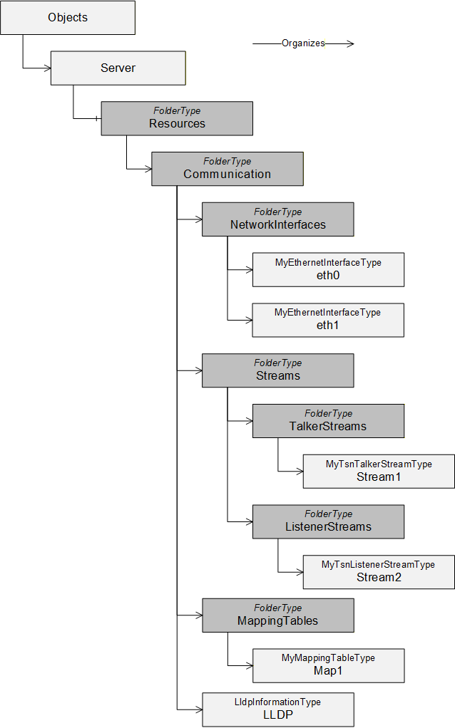
5.4.1 Resources Folder
The Resources Object shall be used as the browse entry point for physical and logical resources of the device the Server is running on. It shall reside in the Server Object defined in OPC 10000-5. It can contain a set of Organizes References that point to other Objects representing specific resources. It is formally defined in Table 50.
| Attribute | Value | ||
| BrowseName | Resources | ||
| References | NodeClass | BrowseName | Comment |
|---|---|---|---|
| ComponentOf of the Server Object defined in Part 5. | |||
| HasTypeDefinition | ObjectType | FolderType | |
| Organizes | Object | Communication | Defined in 5.4.2 |
| Conformance Units | |||
|---|---|---|---|
| BNM Entry Points |
5.4.2 Communication Folder
The Communication Object shall be used as the browse entry point for communication related resources of the physical device the Server is running on. It is formally defined in Table 51.
The Communication Object is referenced by an Organizes Reference from the Resources Object defined in 5.4.1.
The Communication Object can include the following subfolders:
MappingTables
NetworkInterfaces
Streams
Additionally, the Communication Object may include the LLDP instance.
| Attribute | Value | ||
| BrowseName | Communication | ||
| References | NodeClass | BrowseName | Comment |
|---|---|---|---|
| HasTypeDefinition | ObjectType | FolderType | |
| Organizes | Object | MappingTables | Defined in 5.4.3 |
| Organizes | Object | NetworkInterfaces | Defined in 5.4.4 |
| Organizes | Object | Streams | Defined in 5.4.5 |
| Organizes | Object | LLDP | Defined in 5.4.8 |
| Conformance Units | |||
|---|---|---|---|
| BNM Entry Points |
5.4.3 MappingTables Folder
The MappingTables Object shall be used as the browse entry point for mapping tables of priority values and their application labels. It is formally defined in Table 52 – MappingTables definition. All instances of the PriorityMappingTableType shall be referenced from this Object, either directly or indirectly, following hierarchical References.
| Attribute | Value | ||
| BrowseName | MappingTables | ||
| References | NodeClass | BrowseName | Comment |
|---|---|---|---|
| HasTypeDefinition | ObjectType | FolderType |
| Conformance Units | |||
|---|---|---|---|
| BNM Mapping Entry Points |
5.4.4 NetworkInterfaces Folder
The NetworkInterfaces Object shall be used as the browse entry point for network interfaces of the device the Server is running on. It is formally defined in Table 53.
| Attribute | Value | ||
| BrowseName | NetworkInterfaces | ||
| References | NodeClass | BrowseName | Comment |
|---|---|---|---|
| HasTypeDefinition | ObjectType | FolderType |
| Conformance Units | |||
|---|---|---|---|
| BNM Entry Points |
The NetworkInterfaces folder is intended to hold instances, which are of IetfBaseNetworkInterfaceType or a subtype of it. However other Objects can be stored within this folder that implement the UA Interface IIetfBaseNetworkInterfaceType.
All Objects of Type IetfBaseNetworkInterfaceType within the NetworkInterfaces folder shall represent either a physical or virtual network interface.
5.4.5 Streams Folder
The Streams Object shall be used as the browse entry point for network streams of the device the Server is running on. It is formally defined in Table 54.
| Attribute | Value | ||
| BrowseName | Streams | ||
| References | NodeClass | BrowseName | Comment |
|---|---|---|---|
| HasTypeDefinition | ObjectType | FolderType | |
| Organizes | Object | TalkerStreams | Defined in 5.4.6 |
| Organizes | Object | ListenerStreams | Defined in 5.4.7 |
| Conformance Units | |||
|---|---|---|---|
| BNM TSN Entry Points |
5.4.6 TalkerStreams Folder
The TalkerStreams Object shall be used as the browse entry point for sending network streams of the device the Server is running on. It is formally defined in Table 55.
| Attribute | Value | ||
| BrowseName | TalkerStreams | ||
| References | NodeClass | BrowseName | Comment |
|---|---|---|---|
| HasTypeDefinition | ObjectType | FolderType |
| Conformance Units | |||
|---|---|---|---|
| BNM TSN Entry Points |
5.4.7 ListenerStreams Folder
The ListenerStreams Object shall be used as the browse entry point for receiving network streams of the device the Server is running on. It is formally defined in Table 56.
| Attribute | Value | ||
| BrowseName | ListenerStreams | ||
| References | NodeClass | BrowseName | Comment |
|---|---|---|---|
| HasTypeDefinition | ObjectType | FolderType |
| Conformance Units | |||
|---|---|---|---|
| BNM TSN Entry Points |
5.4.8 LLDP Information Object
The LLDP Information Object shall be used as the single browse entry point for all LLDP information represented in the Server running on the device. It is formally defined in Table 57.
| Attribute | Value | ||
| BrowseName | LLDP | ||
| References | NodeClass | BrowseName | Comment |
|---|---|---|---|
| HasTypeDefinition | ObjectType | LldpInformationType |
| Conformance Units | |||
|---|---|---|---|
| BNM IEEE LLDP Info |
5.5 ObjectTypes
5.5.1 IetfBaseNetworkInterfaceType
5.5.1.1 Overview
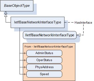
The IetfBaseNetworkInterfaceType defines the core set of properties needed to model a network interface based on the definition provided by IETF. Figure 4 illustrates the structure of the IetfBaseNetworkInterfaceType.
5.5.1.2 IetfBaseNetworkInterfaceType definition
The IetfBaseNetworkInterfaceType is formally defined in Table 58.
| Attribute | Value | ||||
| BrowseName | IetfBaseNetworkInterfaceType | ||||
| IsAbstract | False | ||||
| References |
Node
Class | BrowseName | DataType | TypeDefinition | Other |
|---|---|---|---|---|---|
| Subtype of the BaseObjectType | |||||
| HasInterface | ObjectType | IIetfBaseNetworkInterfaceType | |||
| Applied from IIetfBaseNetworkInterfaceType (see 5.2.1) | |||||
| HasComponent | Variable | AdminStatus | InterfaceAdminStatus | BaseDataVariableType | M |
| HasComponent | Variable | OperStatus | InterfaceOperStatus | BaseDataVariableType | M |
| HasComponent | Variable | PhysAddress | String | BaseDataVariableType | O |
| HasComponent | Variable | Speed | UInt64 | AnalogUnitType | M |
| HasLowerLayerInterface | Object | <InterfaceName> | BaseObjectType | OP | |
| Conformance Units | |||||
|---|---|---|---|---|---|
| BNM IETF Interface Base Info |
The BrowseName of this Object shall be the same as the ifName of the corresponding IETF object (ifName is defined in IETF RFC 2863: The Interfaces Group MIB).
For the formal definition of AdminStatus, OperStatus, PhysAddress and Speed please refer to 5.2.1.
The HasLowerLayerInterface Reference points to an Object implementing the IIetfBaseNetworkInterfaceType used to indicate a hierarchical connection of network interfaces. This is used to indicate the relation e.g. between a VLAN interface and the actual physical interface. A VLAN interface shall additionally implement IVlanIdType.
Each instance of the IetfBaseNetworkInterfaceType shall point to zero or one instance of PriorityMappingTableType or a subtype using a UsesProrityMappingTable Reference or a subtype. The referenced PriorityMappingTable is used for the prioritisation of network messages injected to the network using this network interface. If an instance of type IetfBaseNetworkInterfaceType has no reference to a PriorityMappingTable, the PriorityMappingTable of the next lower layer interface of type IetfBaseNetworkInterfaceType shall be used. An example for this is shown in Annex A.2 for “eth0.100”.
A network interface is linked for transmission or reception via the BrowseName of the object of type IetfBaseNetworkInterfaceType.
The components of the IetfBaseNetworkInterfaceType have the Attribute values defined in Table 59.
| Source Path | Value Attribute | Description Attribute |
NamespaceUri: http://www.opcfoundation.org/UA/units/un/cefact UnitId: 4337968 | - |
The components of the IetfBaseNetworkInterfaceType have additional References which are defined in Table 60.
| SourceBrowsePath | Reference Type | Is Forward | TargetBrowsePath |
| <InterfaceName> | HasInterface | True | IIetfBaseNetworkInterfaceType |
5.5.2 PriorityMappingTableType
5.5.2.1 Overview
Instances of the PriorityMappingTableType contains priority mapping information. Figure 5 illustrates the structure of the PriorityMappingTableType.
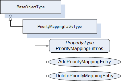
5.5.2.2 PriorityMappingTableType definition
The PriorityMappingTableType is formally defined in Table 61.
| Attribute | Value | ||||
| BrowseName | PriorityMappingTableType | ||||
| IsAbstract | False | ||||
| References |
Node
Class | BrowseName | DataType | TypeDefinition | Other |
|---|---|---|---|---|---|
| Subtype of the BaseObjectType defined in OPC 10000-5 | |||||
| HasProperty | Variable | PriorityMapppingEntries | PriorityMappingEntryType[] | PropertyType | M |
| HasComponent | Method | AddPriorityMappingEntry | Defined in 5.5.2.3 | O | |
| HasComponent | Method | DeletePriorityMappingEntry | Defined in 5.5.2.4 | O | |
| Conformance Units | |||||
|---|---|---|---|---|---|
| BNM Priority Mapping 2 |
PriorityMappingEntries represents a list of all instances of PriorityMappingEntryType. For a formal definition see 5.3.2.1. The order of the elements in the array does not have any influence, as elements are indexed via the MappingUri and PriorityLabel.
The combination of QosCategory and PriorityLabel are used as indices into the referenced PriorityMappingTable to look up the priority values. The reference from an IetfBaseNetworkInterface is described in Section 5.5.1. For the sender, the priority values shall be included within the frame, if the according fields are available, i.e., VLAN Tag to use the PCP value and IP header to use the DSCP value. The receiver can use the priority values for internal packet processing.
AddPriorityMappingEntry allows to add an entry to this instance of PriorityMappingTableType.
DeletePriorityMappingEntry allows to delete an entry from this instance of PriorityMappingTableType.
5.5.2.3 AddPriorityMappingEntry method
This optional Method allows to add an entry to this instance of PriorityMappingTableType. If the combination of MappingUri and PriorityLabel does not exist yet, the element will be added to the Variable PriorityMappingEntries.
The signature of this Method is specified below. Table 62 and Table 64 specify the Arguments and AddressSpace representation, respectively.
Signature
	AddPriorityMappingEntry(
	 [in]  String MappingUri,
	 [in]  String PriorityLabel,
	 [in]  Byte PriorityValue_PCP,
	 [in]  UInt32 PriorityValue_DSCP
);| Argument | Description |
| MappingUri | Named identifier of a well-known predefined set of priority labels. |
| PriorityLabel | Textual representation of the desired transport priority. |
| PriorityValue_PCP |
PriorityValue_PCP shall be a value between 0 and 7. The value 0xFF indicates to omit the PriorityValue_PCP from the entry. |
| PriorityValue_DSCP |
PriorityValue_DSCP shall be a value between 0 and 63. The value 0xFFFFFFFF indicates to omit the PriorityValue_PCP from the entry. |
The possible Method result codes are defined in Table 63.
| ResultCode | Description |
| Bad_UserAccessDenied | The caller is not allowed to add a priority mapping rule. |
| Bad_InvalidArgument | One of the arguments is invalid. |
| Bad_IndexRangeInvalid | A mapping table entry with MappingUri and PriorityLabel already exists. |
| Attribute | Value | ||||
| BrowseName | AddPriorityMappingEntry | ||||
| References | Node Class | BrowseName | DataType | TypeDefinition | Other |
| HasProperty | Variable | InputArguments | Argument[] | PropertyType | M |
5.5.2.4 DeletePriorityMappingEntry method
This optional Method allows to delete an entry from this instance of PriorityMappingTableType.
The signature of this Method is specified below. Table 65 and Table 67 specify the Arguments and AddressSpace representation, respectively.
Signature
	DeletePriorityMappingEntry(
	 [in]  String MappingUri,
	 [in]  String PriorityLabel
);| Argument | Description |
| MappingUri | Named identifier of a well-known predefined set of priority labels. |
| PriorityLabel | Textual representation of the desired transport priority. |
The possible Method result codes are defined in Table 66.
| ResultCode | Description |
| Bad_UserAccessDenied | The caller is not allowed to delete the priority mapping rule. |
| Bad_InvalidState | The state of this ConnectionConfigurationSetType instance is “Processing”. |
| Bad_BrowseNameInvalid | The BrowseName for the mapping entry is invalid. |
| Attribute | Value | ||||
| BrowseName | DeletePriorityMappingEntry | ||||
| References | Node Class | BrowseName | DataType | TypeDefinition | Other |
|---|---|---|---|---|---|
| HasProperty | Variable | InputArguments | Argument[] | PropertyType | M |
5.5.3 LldpInformationType definition
An instance of the LldpInformationType contains LLDP information collected by an independent LLDP agent. Figure 6 illustrates the structure of the LldpInformationType.
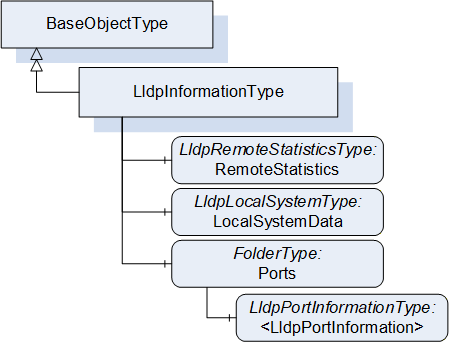
The LldpInformationType is formally defined in Table 68.
| Attribute | Value | ||||
| BrowseName | LldpInformationType | ||||
| IsAbstract | False | ||||
| References |
Node
Class | BrowseName | DataType | TypeDefinition | Other |
|---|---|---|---|---|---|
| Subtype of the BaseObjectType | |||||
| HasComponent | Object | RemoteStatistics | LldpRemoteStatisticsType | O | |
| HasComponent | Object | LocalSystemData | LldpLocalSystemType | M | |
| HasComponent | Object | Ports | FolderType | M | |
| Conformance Units | |||||
|---|---|---|---|---|---|
| BNM IEEE LLDP Info |
LldpInformationType represents the schema of the YANG container lldp in IEEE 802.1ABcu-2021. It models the two entry points for subsequent structures LocalSystemData for all device-related identification and Ports for the port-specific identification and information on neighbour devices.
RemoteStatistics contains a collection of statistics indicating activity and events occurring on neighbour devices.
LocalSystemData represents all device-related identification properties.
Ports is a folder containing one or more instances of LldpPortInformationType that contains information about neighbouring devices seen through that port. The content of Ports is limited to instances of Type LldpPortInformationType.
The components of the LldpInformationType have additional subcomponents, which are defined in Table 69.
| BrowsePath | References | NodeClass | BrowseName | DataType | TypeDefinition | Other |
| Ports | Organizes | Object | <LldpPortInformation> | LldpPortInformationType | OP |
5.5.4 LldpRemoteStatisticsType definition
The LldpRemoteStatisticsType is formally defined in Table 70.
| Attribute | Value | ||||
| BrowseName | LldpRemoteStatisticsType | ||||
| IsAbstract | False | ||||
| References |
Node
Class | BrowseName | DataType | TypeDefinition | Other |
|---|---|---|---|---|---|
| Subtype of the BaseObjectType | |||||
| HasComponent | Variable | LastChangeTime | UInt32 | BaseDataVariableType | M |
| HasComponent | Variable | RemoteInserts | UInt32 | BaseDataVariableType | M |
| HasComponent | Variable | RemoteDeletes | UInt32 | BaseDataVariableType | M |
| HasComponent | Variable | RemoteDrops | UInt32 | BaseDataVariableType | M |
| HasComponent | Variable | RemoteAgeouts | UInt32 | BaseDataVariableType | M |
| Conformance Units | |||||
|---|---|---|---|---|---|
| BNM IEEE LLDP Info |
LldpRemoteStatisticsType represents the schema of the YANG container remote-statistics in IEEE 802.1ABcu-2021.
LastChangeTime defines the time any remote info changed in the scale of the uptime of the system, as defined in clause 11.5.1 of IEEE Std 802.1AB-2016: lldpV2StatsRemTablesLastChangeTime. The uptime of the system is specified by IETF RFC 3418 in the unit of hundreths of a second.
RemoteInserts defines the number of times new information was inserted into the LldpRemoteSystemsType array, as defined in clause 11.5.1 of IEEE Std 802.1AB-2016: lldpV2StatsRemTablesInserts. When this counter reaches the end of its range, it rolls over to 0.
RemoteDeletes defines the number of times information was deleted from the LldpRemoteSystemsType array, as defined in clause 11.5.1 of IEEE Std 802.1AB-2016: lldpV2StatsRemTablesDeletes. When this counter reaches the end of its range, it rolls over to 0.
RemoteDrops defines the number of times new information could not be inserted into the LldpRemoteSystemsType array because of insufficient resources, as defined in clause 11.5.1 of IEEE Std 802.1AB-2016: lldpV2StatsRemTablesDrops. When this counter reaches the end of its range, it rolls over to 0.
RemoteAgeouts defines the number of times information aged out from the LldpRemoteSystemsType array because the information timeliness interval has expired, as defined in clause 11.5.1 of IEEE Std 802.1AB-2016: lldpV2StatsRemTablesAgeouts. When this counter reaches the end of its range, it rolls over to 0.
5.5.5 LldpLocalSystemType definition
The LldpLocalSystemType is formally defined in Table 71.
| Attribute | Value | ||||
| BrowseName | LldpLocalSystemType | ||||
| IsAbstract | False | ||||
| References |
Node
Class | BrowseName | DataType | TypeDefinition | Other |
|---|---|---|---|---|---|
| Subtype of the BaseObjectType | |||||
| HasProperty | Variable | ChassisIdSubtype | ChassisIdSubtype | PropertyType | M |
| HasProperty | Variable | ChassisId | String | PropertyType | M |
| HasProperty | Variable | SystemName | String | PropertyType | M |
| HasProperty | Variable | SystemDescription | String | PropertyType | M |
| HasProperty | Variable | SystemCapabilitiesSupported | LldpSystemCapabilitiesMap | PropertyType | O |
| HasProperty | Variable | SystemCapabilitiesEnabled | LldpSystemCapabilitiesMap | PropertyType | O |
| Conformance Units | |||||
|---|---|---|---|---|---|
| BNM IEEE LLDP Info |
LldpLocalSystemType represents the schema of the YANG container local-system-data in IEEE 802.1ABcu-2021.
ChassisIdSubtype defines type of encoding used to identify the chassis associated with the local system, as defined in clause 8.5.2.2 of IEEE Std 802.1AB-2016.
ChassisId defines the chassis component associated with the local system, as defined in clause 8.5.2.3 of IEEE Std 802.1AB-2016.
SystemName defines the system name of the local system, as defined in clause 8.5.6.2 of IEEE Std 802.1AB-2016.
SystemDescription defines the system description of the local system, as defined in clause 8.5.7.2 of IEEE Std 802.1AB-2016.
SystemCapabilitiesSupported defines the system capabilities that are supported on the local system, as defined in clause 8.5.8.1 of IEEE Std 802.1AB-2016.
SystemCapabilitiesEnabled defines the system capabilities that are enabled on the local system, as defined in clause 8.5.8.2 of IEEE Std 802.1AB-2016.
5.5.6 LldpPortInformationType definition
The LldpPortInformationType is formally defined in Table 72.
| Attribute | Value | ||||
| BrowseName | LldpPortInformationType | ||||
| IsAbstract | False | ||||
| References |
Node
Class | BrowseName | DataType | TypeDefinition | Other |
|---|---|---|---|---|---|
| Subtype of the BaseObjectType | |||||
| HasProperty | Variable | IetfBaseNetworkInterfaceName | String | PropertyType | M |
| HasProperty | Variable | DestMacAddress | Byte[6] | PropertyType | M |
| HasProperty | Variable | PortIdSubtype | PortIdSubtype | PropertyType | M |
| HasProperty | Variable | PortId | String | PropertyType | M |
| HasProperty | Variable | PortDescription | String | PropertyType | O |
| HasProperty | Variable | ManagementAddressTxPort | LldpManagementAddressTxPortType[] | PropertyType | O |
| HasComponent | Object | RemoteSystemsData | FolderType | O | |
| Conformance Units | |||||
|---|---|---|---|---|---|
| BNM IEEE LLDP Info |
LldpPortInformationType represents the schema of the YANG list port in IEEE 802.1Abcu-2021.
IetfBaseNetworkInterfaceName points to an object of type IetfBaseNetworkInterfaceType organized in the NetworkInterfaces folder with the value of the String. This link is needed to identify the port component (contained in the local chassis with the LLDP agent) associated with this entry. Annex A.3 visualizes this reference.
DestMacAddress defines the MAC address of this network interface.
PortIdSubtype defines type of encoding used to identify the associated PortId, as defined in clause 8.5.3.2 of IEEE Std 802.1AB-2016.
PortId defines the port component associated with a given port in the local system, as defined in clause 8.5.3.3 of IEEE Std 802.1AB-2016.
PortDescription defines the port description associated with the local system, as defined in clause 8.5.5.2 of IEEE Std 802.1AB-2016.
ManagementAddressTxPort defines the set of ports (represented as a List of Type LldpManagementAddressTxPortType) on which the local system management address instance will be transmitted.
RemoteSystemsData defines the data received on this particular physical network connection. It is a folder containing instances of type LldpRemoteSystemType.
The components of the LldpInformationType have additional subcomponents, which are defined in Table 73.
| BrowsePath | References | NodeClass | BrowseName | DataType | TypeDefinition | Other |
| RemoteSystemsData | Organizes | Object | <LldpRemoteSystem> | LldpRemoteSystemType | OP |
5.5.7 LldpRemoteSystemType definition
The LldpRemoteSystemType is formally defined in Table 74.
| Attribute | Value | ||||
| BrowseName | LldpRemoteSystemType | ||||
| IsAbstract | False | ||||
| References |
Node
Class | BrowseName | DataType | TypeDefinition | Other |
|---|---|---|---|---|---|
| Subtype of the BaseObjectType | |||||
| HasComponent | Variable | TimeMark | UInt32 | BaseDataVariableType | M |
| HasComponent | Variable | RemoteIndex | UInt32 | BaseDataVariableType | M |
| HasComponent | Variable | ChassisIdSubtype | ChassisIdSubtype | BaseDataVariableType | M |
| HasComponent | Variable | ChassisId | String | BaseDataVariableType | M |
| HasComponent | Variable | PortIdSubtype | PortIdSubtype | BaseDataVariableType | M |
| HasComponent | Variable | PortId | String | BaseDataVariableType | M |
| HasComponent | Variable | PortDescription | String | BaseDataVariableType | O |
| HasComponent | Variable | SystemName | String | BaseDataVariableType | O |
| HasComponent | Variable | SystemDescription | String | BaseDataVariableType | O |
| HasComponent | Variable | SystemCapabilitiesSupported | LldpSystemCapabilitiesMap | BaseDataVariableType | O |
| HasComponent | Variable | SystemCapabilitiesEnabled | LldpSystemCapabilitiesMap | BaseDataVariableType | O |
| HasComponent | Variable | RemoteChanges | Boolean | BaseDataVariableType | O |
| HasComponent | Variable | RemoteTooManyNeighbors | Boolean | BaseDataVariableType | O |
| HasComponent | Variable | ManagementAddress | LldpManagementAddressType[] | BaseDataVariableType | O |
| HasComponent | Variable | RemoteUnknownTlv | LldpTlvType[] | BaseDataVariableType | O |
| Conformance Units | |||||
|---|---|---|---|---|---|
| BNM IEEE LLDP Info |
LldpRemoteSystemType represents the schema of the YANG list remote-systems-data in IEEE 802.1ABcu-2021. These instances are populated based on received LLDP TLVs.
TimeMark defines a TimeFilter for this entry, as defined in IETF RFC 2021 section 6. The units for this time are hundredths of seconds.
RemoteIndex defines an arbitrary local integer value used to identify a remote system, as defined in clause 11.5.1 of IEEE Std 802.1AB-2016: lldpV2RemIndex.
ChassisIdSubtype defines type of encoding used to identify the chassis associated with the remote system, as defined in clause 8.5.2.2 of IEEE Std 802.1AB-2016.
ChassisId defines the chassis component associated with the remote system, as defined in clause 8.5.2.3 of IEEE Std 802.1AB-2016.
PortIdSubtype defines type of encoding used to identify the associated PortId, as defined in clause 8.5.3.2 of IEEE Std 802.1AB-2016.
PortId defines the port component associated with a given port in the remote system, as defined in clause 8.5.3.3 of IEEE Std 802.1AB-2016.
PortDescription defines the port description associated with the remote system, as defined in clause 8.5.5.2 of IEEE Std 802.1AB-2016.
SystemName defines the system name of the remote system, as defined in clause 8.5.6.2 of IEEE Std 802.1AB-2016.
SystemDescription defines the system description of the remote system, as defined in clause 8.5.7.2 of IEEE Std 802.1AB-2016.
SystemCapabilitiesSupported defines the system capabilities are supported on the remote system, as defined in clause 8.5.8.1 of IEEE Std 802.1AB-2016.
SystemCapabilitiesEnabled defines the system capabilities are enabled on the remote system, as defined in clause 8.5.8.2 of IEEE Std 802.1AB-2016.
RemoteChanges Indicates that there are changes in the remote system's data, as determined by the variable remoteChanges, as defined in clause 9.2.5.11 of IEEE Std 802.1AB-2016.
RemoteTooManyNeighbors Indicates that there are too many neighbors as determined by the variable tooManyNeighbors, as defined in clause 9.2.5.15 of IEEE Std 802.1AB-2016.
ManagementAddress defines the Management address information about a particular chassis component (represented as a List of Type LldpManagementAddressType).
RemoteUnknownTlv defines Information about an unrecognized TLV received from a physical network connection.
All values get initialized from the LLDP stack based on received TLVs. If mandatory variables are not initialized due to a non-conforming LLDP stack, the return value for Browse action shall be Bad_NoValue, as defined in OPC 10000-4.
5.6 ReferenceTypes
5.6.1 UsesPriorityMappingTable ReferenceType
The UsesPriorityMappingTable ReferenceType is a concrete ReferenceType and can be used directly. It is a subtype of NonHierarchicalReferences ReferenceType.
The SourceNode of this ReferenceType shall be an Object implementing the IIetfBaseNetworkInterfaceType or an Object of Type IetfBaseNetworkInterfaceType. Each Node shall be the SourceNode of at most one UsesPriorityMappingTable Reference.
The TargetNode of this ReferenceType shall be an instance of PriorityMappingTableType.
The UsesPriorityMappingTable ReferenceType is formally defined in Table 75.
| Attributes | Value | ||
| BrowseName | UsesPriorityMappingTable | ||
| InverseName | UsedByNetworkInterface | ||
| Symmetric | False | ||
| IsAbstract | False | ||
| References | NodeClass | BrowseName | Comment |
|---|---|---|---|
| Subtype of the NonHierarchicalReferences ReferenceType defined in OPC 10000-5 | |||
| Conformance Units | |||
|---|---|---|---|
| BNM Priority Mapping 2 |
5.6.2 HasLowerLayerInterface ReferenceType
The HasLowerLayerInterface ReferenceType is a concrete ReferenceType and can be used directly. It is a subtype of HierarchicalReferences ReferenceType.
The usage of the References is following the YANG modelling approach which is using reference pointers in the YANG-interface nodes to point to other interface nodes in lower or higher layers (“lower-layer-if”, “higher-layer-if”). The YANG Data Model for Interface Management is defined in IETF RFC 8343.
Virtual interfaces shall reference their physical interfaces with the HasLowerLayerInterfaceReferenceType. Annex A contains examples for such hierarchical references.
The SourceNode of this ReferenceType shall be an Object organized in the NetworkInterfaces folder.
The TargetNode of this ReferenceType shall be an Object organized in the NetworkInterfaces folder.
The HasLowerLayerInterface ReferenceType is formally defined in Table 76.
| Attributes | Value | ||
| BrowseName | HasLowerLayerInterface | ||
| InverseName | HasHigherLayerInterface | ||
| Symmetric | False | ||
| IsAbstract | False | ||
| References | NodeClass | BrowseName | Comment |
|---|---|---|---|
| Subtype of the HierarchicalReferences ReferenceType defined in OPC 10000-5 | |||
| Conformance Units | |||
|---|---|---|---|
| BNM IETF Interface Base Info |