
6.6 CncChannelType
6.6.1 General
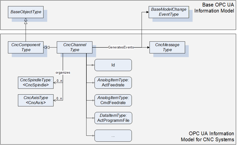
This OPC UA ObjectType represents a CNC channel with all its necessary elements. All Objects of Type CncChannelType are listed in the CncChannelList of the CncInterface Object.
Additionally to data that is relevant for a CNC Channel, CncChannelType organizes Objects of type CncAxisType and CncSpindleType. That is to indicate which components are currently administrated by this channel.
Objects of CncChannelType may generate two kinds of events: Events of type CncMessageType and of type GeneralModelChangeEventType.
Events of Type CncMessageType are used to provide channel specific messages that are not an alarm but an uncritical information, e.g. a user created message out of the CNC part program.
Events of type GeneralModelChangeEventType are used to inform about changes in the Information Model. Examples for the need of a model change event:
A CNC channel can administrate a different set of components during runtime, meaning that an axis or a spindle can change its channel affiliation during runtime of the CNC system; for instance this may be the case if one spindle is used in combination with different axis groups.
Spindles allow different kind of operation modes, for instance a spindle can change its mode of operation from speed to position control and therefore has to be represented once as spindle (CncSpindleType) and once as rotational axis (CncAxisType).
Instances of CncChannelType provide the position of the channel’s tool center point in different coordinate systems. Therefore, the following definitions have to be considered:
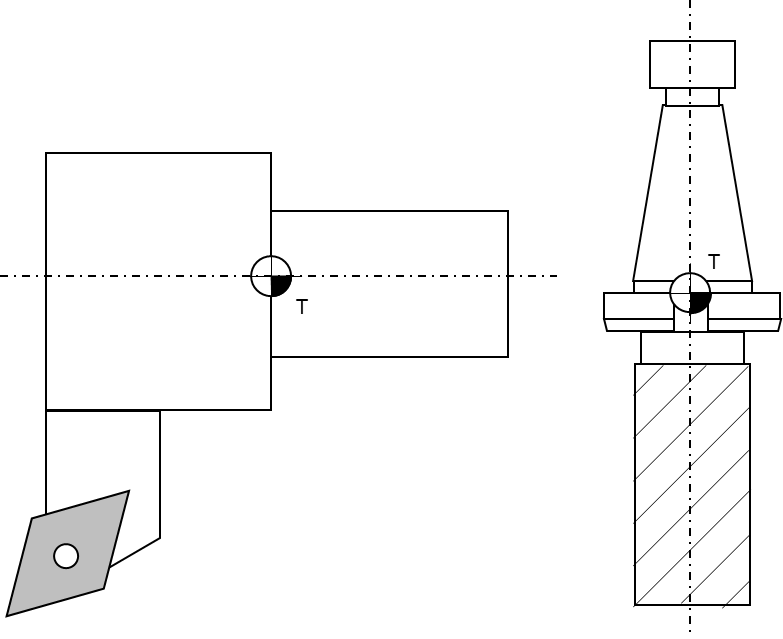
Tool carrier zero point: The tool carrier zero point is a reference point on the tool carrier as illustrated in Figure 10.
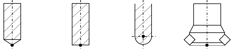
Tool center point: The tool center point of tools for milling operations is usually the intersection of the tool centerline and the lowest positioned cutting tip (edge). For turning operations the tool center point is an imaginary tool point of the cutting insert, because most tools have a cutting edge with a built-in radius. The tool center point of point-to-point tools, such as drills, is the extreme tip of the tool, as measured along the Z axis. Figure 11 and Figure 12 illustrate some common tool center points.

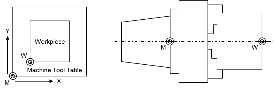
Machine tool coordinate systems: This companion standard refers to two coordinate systems (see Figure 13 for illustration):
Base coordinate system: The base coordinate system (BCS) is a coordinate system defined by the machine tool manufacturer. It has its origin within the machine tool’s zero point M.
Workpiece coordinate system: The workpiece coordinate system (WCS) is a user defined coordinate system and allows considering the clamping position and orientation of a workpiece. It has its origin within the workpiece zero point W.
The coordinate systems are built based on the right-hand-rule, illustrated in Figure 14.
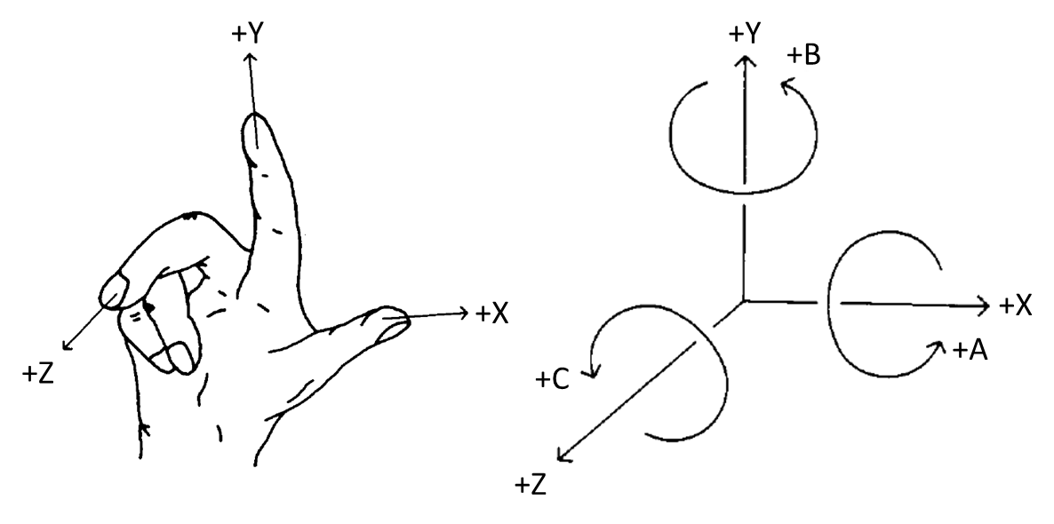
Figure 15 shows an overview for the CncChannelType. It is formally defined in Table 12.
6.6.2 ObjectType Definition
The CncChannelType is formally defined in Table 12.
| Attribute | Value | ||||
| BrowseName | CncChannelType | ||||
| IsAbstract | False | ||||
| References | NodeClass | BrowseName | DataType | TypeDefinition | ModellingRule |
|---|---|---|---|---|---|
| Inherit the components of the CncComponentType | |||||
| GeneratesEvent | ObjectType | CncMessageType | |||
| GeneratesEvent | ObjectType | GeneralModel ChangeEventType | |||
| HasProperty | Variable | 0:NodeVersion | String | PropertyType | Optional |
| HasComponent | Object | <CncAxis> | CncAxisType | OptionalPlaceholder | |
| HasComponent | Object | <CncSpindle> | CncSpindleType | OptionalPlaceholder | |
| HasComponent | Variable | ActFeedrate | Double | AnalogItemType | Mandatory |
| HasComponent | Variable | ActGFunctions | UInt32[] | DataItemType | Mandatory |
| HasComponent | Variable | ActJogIncrement | Double | AnalogItemType | Mandatory |
| HasComponent | Variable | ActMainProgramFile | String | DataItemType | Mandatory |
| HasComponent | Variable | ActMainProgramFileOffset | UInt32 | DataItemType | Optional |
| HasComponent | Variable | ActMainProgramLine | String | DataItemType | Optional |
| HasComponent | Variable | ActMainProgramName | String | DataItemType | Mandatory |
| HasComponent | Variable | ActMFunctions | UInt32[] | DataItemType | Mandatory |
| HasComponent | Variable | ActModalOffsetFunction | UInt32 | DataItemType | Mandatory |
| HasComponent | Variable | ActOperationMode | CncOperationMode | DataItemType | Mandatory |
| HasComponent | Variable | ActOverride | Double | AnalogItemType | Mandatory |
| HasComponent | Variable | ActProgramBlock | String[] | DataItemType | Mandatory |
| HasComponent | Variable | ActProgramFile | String | DataItemType | Mandatory |
| HasComponent | Variable | ActProgramFileOffset | UInt32 | DataItemType | Optional |
| HasComponent | Variable | ActProgramLine | String | DataItemType | Optional |
| HasComponent | Variable | ActProgramName | String | DataItemType | Mandatory |
| HasComponent | Variable | ActProgramStatus | CncChannelProgStatus | DataItemType | Mandatory |
| HasComponent | Variable | ActStatus | CncChannelStatus | DataItemType | Mandatory |
| HasComponent | Variable | BlockMode | Boolean | DataItemType | Mandatory |
| HasComponent | Variable | CmdFeedrate | Double | AnalogItemType | Mandatory |
| HasComponent | Variable | CmdOverride | Double | AnalogItemType | Mandatory |
| HasComponent | Variable | DryRunFeed | Double | AnalogItemType | Mandatory |
| HasComponent | Variable | FeedHold | Boolean | DataItemType | Mandatory |
| HasProperty | Variable | Id | UInt32 | PropertyType | Mandatory |
| HasComponent | Variable | PosTcpBcsA | CncPositionDataType | CncPosition VariableType | Mandatory |
| HasComponent | Variable | PosTcpBcsB | CncPositionDataType | CncPosition VariableType | Mandatory |
| HasComponent | Variable | PosTcpBcsC | CncPositionDataType | CncPosition VariableType | Mandatory |
| HasComponent | Variable | PosTcpBcsX | CncPositionDataType | CncPosition VariableType | Mandatory |
| HasComponent | Variable | PosTcpBcsY | CncPositionDataType | CncPosition VariableType | Mandatory |
| HasComponent | Variable | PosTcpBcsZ | CncPositionDataType | CncPosition VariableType | Mandatory |
| HasComponent | Variable | PosTcpWcsA | CncPositionDataType | CncPosition VariableType | Mandatory |
| HasComponent | Variable | PosTcpWcsB | CncPositionDataType | CncPosition VariableType | Mandatory |
| HasComponent | Variable | PosTcpWcsC | CncPositionDataType | CncPosition VariableType | Mandatory |
| HasComponent | Variable | PosTcpWcsX | CncPositionDataType | CncPosition VariableType | Mandatory |
| HasComponent | Variable | PosTcpWcsY | CncPositionDataType | CncPosition VariableType | Mandatory |
| HasComponent | Variable | PosTcpWcsZ | CncPositionDataType | CncPosition VariableType | Mandatory |
| HasComponent | Variable | ToolId | UInt32 | DataItemType | Mandatory |
6.6.3 ObjectType Description
6.6.3.1 CncMessage
CncChannelType may generate events of type CncMessageType to provide channel specific information messages (for instance triggered out of CNC part program).
6.6.3.2 GeneralModelChangeEvent
CncChannelType may generate events of type GeneralModelChangeEventType defined in OPC 10000-3 to inform Clients when CncSpindle or CncAxis Objects have been added or removed from a CncChannelType instance.
6.6.3.3 NodeVersion
The optional Property NodeVersion shall be present if the Server emits GeneralModelChangeEvents for the Object of type CncChannelType. The NodeVersion Property and the relation to GeneralModelChangeEvents are defined in OPC 10000-3.
6.6.3.4 CncAxis
CNC axis object.
6.6.3.5 CncSpindle
CNC spindle object.
6.6.3.6 ActFeedrate
Feedrate actual value.
6.6.3.7 ActJogIncrement
Active JOG increment, i.e. a position increment that is executed with each user jog command. Usually, there are predefined increments given (1/10, 1/100, 1/1000 position increment in the selected physical unit), but a continuous jog mode and a jog mode with variable increment are possible, too. A continuous jog mode is indicated with a jog increment value of -1, all other jog increments are given as real increments in the appropriate units.
6.6.3.8 ActGFunctions
Array of active G functions; there can be several G functions active at a time (modal and non-modal G functions).
6.6.3.9 ActMainProgramFile
Path of active CNC main program.
6.6.3.10 ActMainProgramFileOffset
File offset of active CNC main program file (corresponds to the number of line feeds).
6.6.3.11 ActMainProgramName
Name of active CNC main program.
6.6.3.12 ActMainProgramLine
Line number of active CNC main program (usually defined as N<Number>).
6.6.3.13 ActMFunctions
Array of active M functions: there can be several M functions active at a time (modal and non-modal M functions).
6.6.3.14 ActModalOffsetFunction
Active zero offset function (usually G54, G55, G56 or G57; G53 repeals zero offsets).
6.6.3.15 ActOperationMode
Channel’s active mode of operation. See 7.2.6 for further description of possible states.
6.6.3.16 ActOverride
Axis override actual value.
6.6.3.17 ActProgramBlock
Block of lines containing the previous, actual and subsequent lines of a CNC part program.
6.6.3.18 ActProgramFile
Path of active CNC part program file (main or subprogram).
6.6.3.19 ActProgramFileOffset
File offset of active CNC part program file (main or subprogram).
6.6.3.20 ActProgramLine
Line number of active CNC part program (main or subprogram).
6.6.3.21 ActProgramName
Name of active CNC part program (main or subprogram).
6.6.3.22 ActProgramStatus
Active channel program status. See 7.2.5 for further description of possible states.
6.6.3.23 ActStatus
Active status of channel. See 7.2.4 for further description of possible states.
6.6.3.24 BlockMode
Block mode status (true in case of block mode is active, else false). With block mode active, individual program blocks are processed one by one. Each step has to be triggered by the operator.
6.6.3.25 CmdFeedrate
Feedrate setpoint value.
6.6.3.26 CmdOverride
Override setpoint value.
6.6.3.27 DryRunFeed
Test federate.
6.6.3.28 FeedHold
Feed status (true in case of feed hold active, else false).
6.6.3.29 Id
Unique numeric channel identifier.
6.6.3.30 PosTcpBcsA
Actual position of the tool center point in machine’s Cartesian base coordinate system. The tool center point is the reference point on a tool how it is considered by the CNC’s tool compensation function. If there is no tool present, the tool center point is the tool carrier zero point.
6.6.3.31 PosTcpBcsB
Actual position of the tool center point in machine’s Cartesian base coordinate system. The tool center point is the reference point on a tool how it is considered by the CNC’s tool compensation function. If there is no tool present, the tool center point is the tool carrier zero point.
6.6.3.32 PosTcpBcsC
Actual position of the tool center point in machine’s Cartesian base coordinate system. The tool center point is the reference point on a tool how it is considered by the CNC’s tool compensation function. If there is no tool present, the tool center point is the tool carrier zero point.
6.6.3.33 PosTcpBcsX
Actual position of the tool center point in machine’s Cartesian base coordinate system. The tool center point is the reference point on a tool how it is considered by the CNC’s tool compensation function. If there is no tool present, the tool center point is the tool carrier zero point.
6.6.3.34 PosTcpBcsY
Actual position of the tool center point in machine’s Cartesian base coordinate system. The tool center point is the reference point on a tool how it is considered by the CNC’s tool compensation function. If there is no tool present, the tool center point is the tool carrier zero point.
6.6.3.35 PosTcpBcsZ
Actual position of the tool center point in machine’s Cartesian base coordinate system. The tool center point is the reference point on a tool how it is considered by the CNC’s tool compensation function. If there is no tool present, the tool center point is the tool carrier zero point.
6.6.3.36 PosTcpWcsA
Actual position of the tool center point in machine’s Cartesian workpiece coordinate system. The tool center point is the reference point on a tool how it is considered by the CNC’s tool compensation function. If there is no tool present, the tool center point is the tool carrier zero point. Hence, the position corresponds to the position programmed in the CNC part program.
6.6.3.37 PosTcpWcsB
Actual position of the tool center point in machine’s Cartesian workpiece coordinate system. The tool center point is the reference point on a tool how it is considered by the CNC’s tool compensation function. If there is no tool present, the tool center point is the tool carrier zero point. Hence, the position corresponds to the position programmed in the CNC part program.
6.6.3.38 PosTcpWcsC
Actual position of the tool center point in machine’s Cartesian workpiece coordinate system. The tool center point is the reference point on a tool how it is considered by the CNC’s tool compensation function. If there is no tool present, the tool center point is the tool carrier zero point. Hence, the position corresponds to the position programmed in the CNC part program.
6.6.3.39 PosTcpWcsX
Actual position of the tool center point in machine’s Cartesian workpiece coordinate system. The tool center point is the reference point on a tool how it is considered by the CNC’s tool compensation function. If there is no tool present, the tool center point is the tool carrier zero point. Hence, the position corresponds to the position programmed in the CNC part program.
6.6.3.40 PosTcpWcsY
Actual position of the tool center point in machine’s Cartesian workpiece coordinate system. The tool center point is the reference point on a tool how it is considered by the CNC’s tool compensation function. If there is no tool present, the tool center point is the tool carrier zero point. Hence, the position corresponds to the position programmed in the CNC part program.
6.6.3.41 PosTcpWcsZ
Actual position of the tool center point in machine’s Cartesian workpiece coordinate system. The tool center point is the reference point on a tool how it is considered by the CNC’s tool compensation function. If there is no tool present, the tool center point is the tool carrier zero point. Hence, the position corresponds to the position programmed in the CNC part program.
6.6.3.42 ToolId
ID of active tool that has been selected (e.g. calling “T1” in the CNC part program). Returns an empty string, if no tool is present.