5 Information Model Overview
5.1 Modelling concepts
The main objective of this companion standard is to have an Information Model that results in a clearly defined and structured CNC data interface. That means that both data items and its composition are specified. Manufacturer and use case specific extensions shall be possible.
Regarding the data elements standard OPC UA Variable types shall be used as far as possible. There are two main categories of data items present: unit based items (e.g. position data in mm or inch) and items without unit (e.g. state data). Unit based items shall be realized as AnalogItemTypes, other data as DataItemTypes. Units shall be used as described in OPC 10000-8.
Regarding the structure of the CNC data interface it is intended to realize flat hierarchies. However, multiple referencing of Objects shall be used for exposing the assignment of components within the hardware or software system.
ObjectTypes shall be derived as far as possible from hardware and software components of a CNC system.
5.2 Model Overview
Based on the modelling concepts this chapter introduces the “OPC UA Information Model for CNC Systems”.
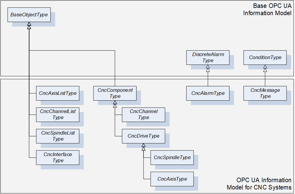
This Information Model provides the ObjectTypes as illustrated in Figure 6. There are ObjectTypes that are used as structuring elements of the CNC data interface (e.g. CncAxisListType) and ObjectTypes to define grouping elements related to hardware and software components of a CNC system (e.g. CncAxisType). Furthermore, this Information Model specifies EventTypes for alarm reporting (e.g. CncAlarmType).
The overall structure of the CNC data interface is illustrated in Figure 7. CncInterface represents the entry point to the CNC data interface. It contains next to the instances of the above mentioned ObjectTypes several Properties for specifying the data interface (e.g. Version, VendorName). One main objective of this Information Model is to provide first of all a fast and easy access to all components managed by the CNC data interface. Out of this reason there are lists provided by the CncInterface Object (e.g. CncAxisList) to allow accessing components without knowing about their affiliation within the logical structure of a machine tool or a CNC system (e.g. independent from their channel affiliation all axes can be accessed via the CncAxisList Object). However, logical structures are additionally modeled by using Hierarchical References (organizes). For instance, a CNC channel of type CncChannelType holds References to all axes and spindles that are assigned to this specific channel, see Figure 7.
The CncInterface Object is furthermore responsible for the alarm and event handling of the CNC data interface. It generates events of type CncAlarmType and CncMessageType for providing error and information messages.
Instances of CncChannelType can generate events of type CncMessageType for providing information messages.
FileSystem represents the entry point to the file system of the CNC data interface. It is subordinated to the CncInterface Object.
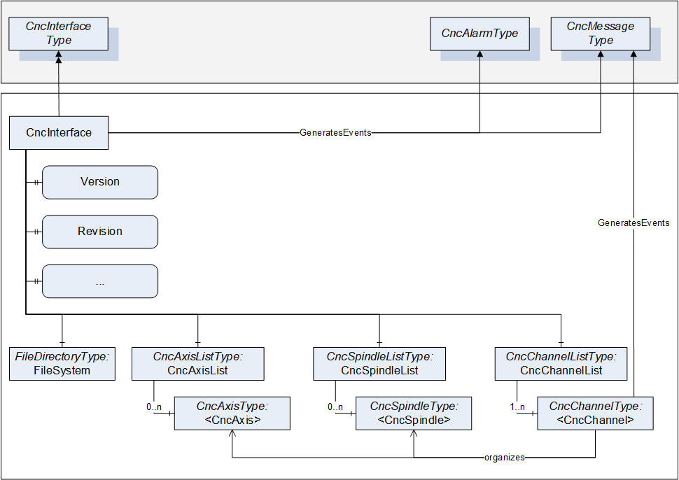
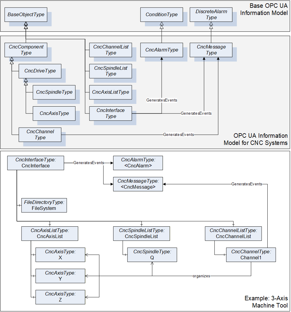
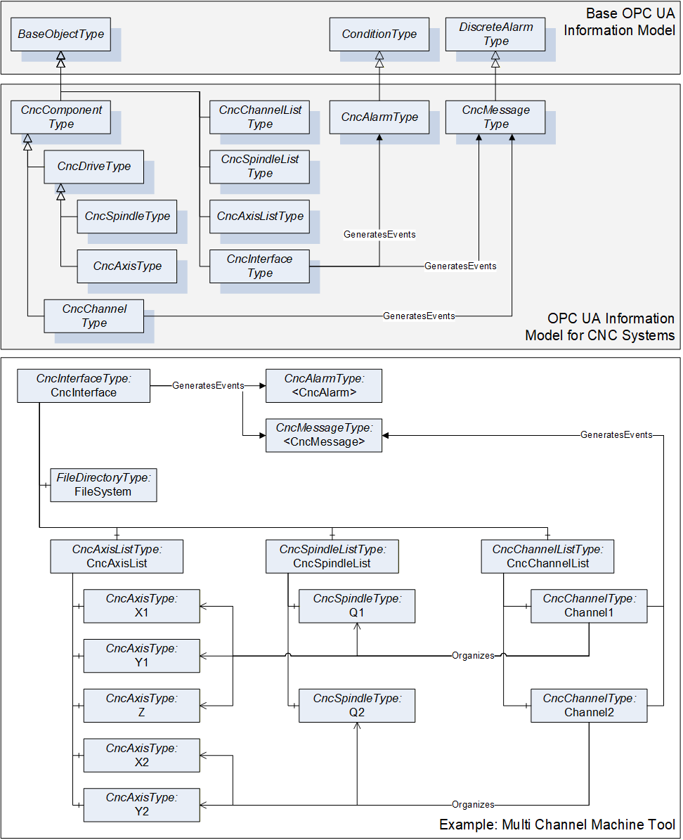
Figure 8 and Figure 9 serves as an example for this companion standard. The shown Information Model is built up for a three axis machine tool and a multi channel machine tool. For the sake of clarity only the ObjectTypes and its References are presented but not its Variables or Properties. For further information, the ObjectTypes are described in detail in chapter 6.