4 General information to CNC systems and OPC UA
4.1 Introduction to CNC systems
4.1.1 General
CNC systems are used to control machine tools and machining centers. The CNC system is mainly responsible for generating a relative movement between a tool (e.g cutting tool) and a workpiece. Therefore, the CNC system implements functionality to provide setpoints to a machine tool's drives that realize the generated movement physically.
CNC systems are in most cases executed in combination with Programmable Logic Controllers (PLC). Whereas the CNC is responsible for the tool path generation, the PLC implements auxiliary functionality (mostly logical operations like activating lubrication at a certain time) and controls the peripheral devices.
CNC systems as a whole consist of several hardware and software components as illustrated in Figure 1.
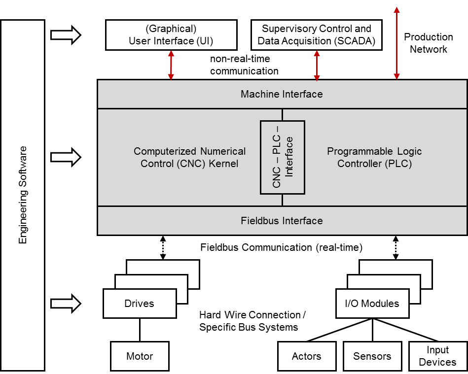
Computerized Numerical Control Kernel (CNC kernel): The CNC kernel realizes the core functionality of a CNC system. It implements functionality to generate the axes movement for machining workpieces based on a geometrical and technological description given in a CNC part program. Therefore it provides software functions for decoding, interpreting and processing data of a CNC part program, for path planning and setpoint generation considering given constraints and depending on the system's realization for positioning the machine's axes.
Programmable Logic Controller (PLC): The PLC handles all logical operations of a CNC system. It is closely coupled with the CNC kernel and enables to realize complex process sequences that involve different actors and sensors of the machine next to the machine's drives. The PLC may also realize monitoring and safety functions and processes input signals from certain devices or the user interface. PLC programs are often implemented according to IEC 61131-3.
CNC-PLC-Interface: The CNC-PLC-Interface links the CNC kernel and the PLC. Both modules have to be synchronized and therefore are closely coupled. The CNC-PLC-Interface is often realized as shared memory to allow high performing data exchange.
Machine Interface: The Machine Interface allows applications to exchange data with a CNC system. Thus, the CNC system can be configured, operated and monitored. The Machine Interface is used primarily by the User Interface (UI) but additionally by other applications like engineering and production management systems. Many CNC systems offer more than one Machine Interface connection point so that different communication mechanisms or protocols can be used at a time.
(Graphical) User Interface (UI): The UI, mostly realized as graphical user interface (GUI) is a software application that allows operators and commissioning engineers to interact with the CNC system and therefore to configure, operate and monitor the CNC system as well as the complete machine tool. The UI is connected to the Machine Interface of the CNC system. It may be executed on the same system platform than the CNC or on a separate device.
Fieldbus Interface: The peripheral devices and the drives of a machine tool are connected to the CNC system by a fieldbus. For that reason both CNC and hardware device provide a Fieldbus Interface for connecting one with another. Most fieldbus systems allow to communicate data in a cyclical, time deterministic behaviour, as well as in an asynchronous mode.
Drives and Motors: The drive unit, consisting of drive and motor, realizes physically the desired tool path, generated by the CNC kernel. The drive implements among others feedback controllers for current, velocity and mostly for position, as well. Generated setpoints are used for controlling the motor. The drive itself is connected to the CNC by a fieldbus to realize a time deterministic communication behaviour.
I/O-Modules and Actors, Sensors, Input Devices: Apart from the drives, other peripheral devices (actors, sensors and input devices) are connected directly or through I/O-Modules to the CNC by a fieldbus.
Machine tools and machining centers can constitute complex systems regarding their kinematic structure. To cope with this complexity CNC systems provide the possibility to fragment the control task by using a software construct organizing kinematic chains and additional moving machine tool components like tool changers. So called "channels" are responsible for controlling smaller portions of the machine tool kinematic and its additional components. In general, all axes within a channel are interpolated in common.
4.1.2 CNC Data
A CNC system provides data through the Machine Interface for external application systems like UIs, SCADA and engineering systems among others. This data has its origin within the CNC system itself or is collected from the drives and peripheral devices. All available data can be divided into the following categories:
Parameter: Configuration data of the CNC system, hardware devices and communication mechanisms. Parameters do not have any requirements regarding communication behaviour.
State data: States of the hardware devices, CNC kernel and PLC. States may be built within the PLC system itself by summarizing data.
Command data: Setpoint values and commands that are communicated from the Machine Interface to the CNC system as well as from the CNC system to the hardware devices. The first do not have requirements regarding the communication behaviour, the latter are communicated cyclically from the CNC system to the appropriate devices.
Process data: Actual values of the hardware devices. Values are communicated cyclically from the appropriate devices to the CNC system.
Alarms: Events of the CNC System, e.g. by the CNC kernel, the PLC, but as well by the UI, informing about errors or other notifications.
Files: Files are transferred from the Machine Interface to the CNC kernel or the PLC, maybe as well to the drives and peripheral devices holding configuration data (e.g. tool parameters) or process information in form of part programs or similar.
4.1.3 Production Network
CNC systems may be integrated in a network comprising various systems for controlling and supervising the production. Hence CNC systems may be connected next to UI and engineering software applications to different systems like
MES,
ERP systems,
PDA/MDA systems,
diagnosis and condition monitoring applications,
further external UI applications, e.g. smart device applications or similar.
A CNC system can be integrated into a production network using the appropriate interface, mostly the Machine Interface. Due to the diversity of systems and system manufacturers standardized interfaces could reduce efforts for linking these systems. This Information Model aims at achieving precisely this objective.
4.1.4 Restrictions
The focus of the "OPC UA Information Model for CNC systems" is on data that is situated within the CNC kernel but not within the PLC of a CNC system. This results out of the main objective of this Information Model to standardize an interface that provides and enables to access clearly defined raw data. Hence this Information Model addresses applications like UIs, PDA/MDA systems, diagnosis and monitoring applications, but not necessarily MES or ERP systems as the two latter ones mostly need summarized data.
For PLC data and in a wider context for MES and ERP data, please refer to suitable standards and OPC UA companion standards like OPC 30000 (PLCopen) or OPC 10030 (ISA 95).
4.2 Introduction to OPC Unified Architecture
4.2.1 General
The main use case for OPC standards is the online data exchange between devices and HMI or SCADA systems using Data Access functionality. In this use case the device data is provided by an OPC server and is consumed by an OPC client integrated into the HMI or SCADA system. OPC DA provides functionality to browse through a hierarchical namespaces containing data items and to read, write and to monitor these items for data changes. The classic OPC standards are based on Microsoft COM/DCOM technology for the communication between software components from different vendors. Therefore classic OPC server and clients are restricted to Windows PC based automation systems.
OPC UA incorporates all features of classic OPC standards like OPC DA, A&E and HDA but defines platform independent communication mechanisms and generic, extensible and object-oriented modelling capabilities for the information a system wants to expose.
The OPC UA network communication part defines different mechanisms optimized for different use cases. The first version of OPC UA is defining an optimized binary TCP protocol for high performance intranet communication as well as a mapping to accepted internet standards like Web Services. The abstract communication model does not depend on a specific protocol mapping and allows adding new protocols in the future. Features like security, access control and reliability are directly built into the transport mechanisms. Based on the platform independence of the protocols, OPC UA servers and clients can be directly integrated into devices and controllers.
The OPC UA Information Model provides a standard way for Servers to expose Objects to Clients. Objects in OPC UA terms are composed of other Objects, Variables and Methods. OPC UA also allows relationships to other Objects to be expressed.
The set of Objects and related information that an OPC UA Server makes available to Clients is referred to as its AddressSpace. The elements of the OPC UA Object Model are represented in the AddressSpace as a set of Nodes described by Attributes and interconnected by References. OPC UA defines eight classes of Nodes to represent AddressSpace components. The classes are Object, Variable, Method, ObjectType, VariableType, DataType, ReferenceType and View. Each NodeClass has a defined set of Attributes.
This specification makes use of three essential OPC UA NodeClasses: Objects, Methods and Variables.
Objects are used to represent components of a system. An Object is associated to a corresponding ObjectType that provides definitions for that Object.
Methods are used to represent commands or services of a system.
Variables are used to represent values. Two categories of Variables are defined, Properties and DataVariables.
Properties are Server-defined characteristics of Objects, DataVariables and other Nodes. Properties are not allowed to have Properties defined for them. An example for Properties of Objects is the Version Property of the CncInterfaceType.
DataVariables represent the contents of an Object. DataVariables may have component DataVariables. This is typically used by Servers to expose individual elements of arrays and structures. This specification uses DataVariables to represent parameters, state data, process and command data, for example ActSpeed of a Object of CncSpindleType.
4.2.2 Graphical Notation
OPC UA defines a graphical notation for an OPC UA AddressSpace. It defines graphical symbols for all NodeClasses and how different types of References between Nodes can be visualized. Figure 2 shows the symbols for the six NodeClasses used in this specification. NodeClasses representing types always have a shadow.
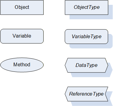
Figure 3 shows the symbols for the ReferenceTypes used in this specification. The Reference symbol is normally pointing from the source Node to the target Node. The only exception is the HasSubtype Reference. The most important References like HasComponent, HasProperty, HasTypeDefinition and HasSubtype have special symbols avoiding the name of the Reference. For other ReferenceTypes or derived ReferenceTypes the name of the ReferenceType is used together with the symbol.
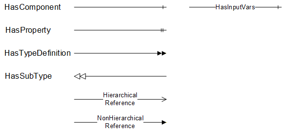
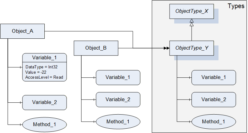
Figure 4 shows a typical example for the use of the graphical notation. Object_A and Object_B are instances of the ObjectType_Y indicated by the HasTypeDefinition References. The ObjectType_Y is derived from ObjectType_X indicated by the HasSubtype Reference. The Object_A has the components Variable_1, Variable_2 and Method_1.
To describe the components of an Object on the ObjectType the same NodeClasses and References are used on the Object and on the ObjectType like for ObjectType_Y in the example. The instance Nodes used to describe an ObjectType are instance declaration Nodes.
To provide more detailed information for a Node, a subset or all Attributes and their values can be added to a graphical symbol.
4.3 Use Cases
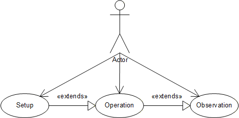
This companion standard is meant to be used for CNC data interfaces. It allows to access data provided by a CNC system, namely parameters, state data, process and command data, alarm notifications and files. Access covers both read and write access. Thus, the following use cases may be covered:
Setup: The CNC data interface provides data that can be used for setting up a production system controlled by a CNC. This refers first of all to production commissioning data (e.g. job description, tool data etc.) but implies to a certain extent as well CNC configuration data (e.g. axis parameters, cycle time etc.), as needed for engineering.
Operation: The CNC data interface may be used for operating a production system controlled by a CNC and therefore serves as a connection point for user interfaces.
Observation: The CNC data interface may be used for observing a production system controlled by a CNC and therefore serves as a connection point for monitoring and diagnosis applications and for user interfaces.
Figure 5 shows the use case diagram.