4 General information to BACnet and OPC UA
4.1 Introduction to BACnet
4.1.1 General
BACnet (Building Automation and Control networks) is a data-communication protocol specifically designed for building automation applications.
1987 the ASHRAE (American Society of Heating, Refrigerating and Air-Conditioning Engineers) founded the committee 135 to create an open and neutral communication protocol for building automation. First published in 1995 the BACnet standard is under continuous maintenance by SSPC 135. A public review process before the formal approval assures acceptance by the industry or interested parties.
While starting as a national American standard BACnet has become a world-wide standard and was accepted by ISO as the standards ISO 16484-5 and ISO 16484-6.
The general architecture of BACnet describes three main parts, the BACnet data link layers, the BACnet objects and the BACnet application services.
4.1.2 BACnet Data-Link-Layers
BACnet supports a total of 9 different network media (data-link-layer).
Those are:
BACnet Ethernet (ISO 8802-3 aka Layer-2 Ethernet, rarely used)
ARCnet (Network or EIA-485, rarely used)
LonTalk (any media supported by LonTalk, rarely used)
MS/TP (Master/Slave Token Passing) based on EIA-485 (serial networks, commonly used)
PTP (Point-to-Point) based on EIA-232 (serial connection, rarely used)
BACnet/IP (based upon IPv4 and UDP communication, commonly used)
BACnet/IPv6 (based upon IPv6 and UDP communication, rarely used)
ZIGBEE (wireless mesh networks, rarely used)
BACnet/SecureConnect (based upon TCP / websocket based communication, rarely used but expected to be commonly used in the future)
4.1.3 BACnet Objects
BACnet models the data of building automation components as objects. Those include Analog, Binary and Multi-State Input, Output and Value Objects, primitive data, the representation of devices, counters, calendar and scheduling, trend-logging, alarming, life-safety and access control objects as well as objects to represent a building structure (groups, structured views).
Objects consist of properties to represent the data associated to the specific information. This includes text information like the name and description, the technical address of the data, the present value, units, alarm-limits as well as specific building automation functionality like command priorities, elapsed active time or change-of-state counting. Due to the de-central approach of BACnet a client can request all information from a device representing data as a server.
4.1.4 BACnet Application Services
The BACnet application services allow access to the objects and provide functions to interact between BACnet applications in a network. Another set of network services on layer 3 of the ISO/OSI model provide routing functions between the different data-link-layers as well as exchanging information about network security.
Application services include object access like reading, writing and change-of-value. Other services provide file-transfer, alarm information, remote device and network management and virtual terminal functions.
To assure interoperability between applications BACnet specifies a PICS (Protocol Implementation Conformance Statement) document. A PICS is a self-declaration by the vendor of a BACnet device and describes which parts of BACnet are supported by the implementation.
4.1.5 BACnet Device Profiles
BACnet devices may support one of the 8 device profiles specified for better interoperability.
The profiles are:
| B-AWS: | Advanced Operator Workstation |
| B-OWS: | Operator Workstation |
| B-OD: | Operator Display |
| B-BC: | Building Controller |
| B-AAC: | Advanced Application Controller |
| B-ASC: | Application specific controller |
| B-SS: | Smart Sensor |
| B-SA: | Smart Actuator |
4.2 Introduction to OPC Unified Architecture
4.2.1 General
The main use case for OPC standards is the online data exchange between devices and HMI or SCADA systems using Data Access functionality. In this use case the device data is provided by an OPC server and is consumed by an OPC client integrated into the HMI or SCADA system. OPC DA provides functionality to browse through a hierarchical namespaces containing data items and to read, write and to monitor these items for data changes. The classic OPC standards are based on Microsoft COM/DCOM technology for the communication between software components from different vendors. Therefore classic OPC server and clients are restricted to Windows PC based automation systems.
OPC UA incorporates all features of classic OPC standards like OPC DA, A&E and HDA but defines platform independent communication mechanisms and generic, extensible and object-oriented modelling capabilities for the information a system wants to expose.
The OPC UA network communication part defines different mechanisms optimized for different use cases. The first version of OPC UA is defining an optimized binary TCP protocol for high performance intranet communication as well as a mapping to accepted internet standards like Web Services. The abstract communication model does not depend on a specific protocol mapping and allows adding new protocols in the future. Features like security, access control and reliability are directly built into the transport mechanisms. Based on the platform independence of the protocols, OPC UA servers and clients can be directly integrated into devices and controllers.
The OPC UA Information Model provides a standard way for Servers to expose Objects to Clients. Objects in OPC UA terms are composed of other Objects, Variables and Methods. OPC UA also allows relationships to other Objects to be expressed.
The set of Objects and related information that an OPC UA Server makes available to Clients is referred to as its AddressSpace. The elements of the OPC UA Object Model are represented in the AddressSpace as a set of Nodes described by Attributes and interconnected by References. OPC UA defines eight classes of Nodes to represent AddressSpace components. The classes are Object, Variable, Method, ObjectType, DataType, ReferenceType and View. Each NodeClass has a defined set of Attributes.
This specification makes use of three essential OPC UA NodeClasses: Objects, Methods and Variables.
Objects are used to represent components of a system. An Object is associated to a corresponding ObjectType that provides definitions for that Object.
Methods are used to represent commands or services of a system.
Variables are used to represent values. Two categories of Variables are defined, Properties and DataVariables.
Properties are Server-defined characteristics of Objects, DataVariables and other Nodes. Properties are not allowed to have Properties defined for them. An example for Properties of Objects is the Object_Identifier Property of a BACnetObjectType.
DataVariables represent the contents of an Object. DataVariables may have component DataVariables. This is typically used by Servers to expose individual elements of arrays and structures. This specification uses DataVariables to represent data like the Present_Value of a BACnetAnalogInput Object.
4.2.2 Graphical Notation
OPC UA defines a graphical notation for an OPC UA AddressSpace. It defines graphical symbols for all NodeClasses and how different types of References between Nodes can be visualized. Figure 1 shows the symbols for the six NodeClasses used in this specification. NodeClasses representing types always have a shadow.
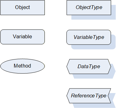
Figure 2 shows the symbols for the ReferenceTypes used in this specification. The Reference symbol is normally pointing from the source Node to the target Node. The only exception is the HasSubType Reference. The most important References like HasComponent, 0:HasProperty, HasTypeDefinition and HasSubType have special symbols avoiding the name of the Reference. For other ReferenceTypes or derived ReferenceTypes the name of the ReferenceType is used together with the symbol.
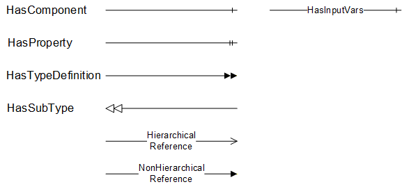
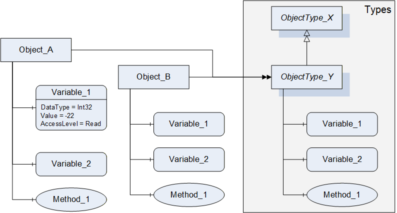
Figure 3 shows a typical example for the use of the graphical notation. Object_A and Object_B are instances of the ObjectType_Y indicated by the HasTypeDefinition References. The ObjectType_Y is derived from ObjectType_X indicated by the HasSubType Reference. The Object_A has the components Variable_1, Variable_2 and Method_1.
To describe the components of an Object on the ObjectType the same NodeClasses and References are used on the Object and on the ObjectType like for ObjectType_Y in the example. The instance Nodes used to describe an ObjectType are instance declaration Nodes.
To provide more detailed information for a Node, a subset or all Attributes and their values can be added to a graphical symbol.
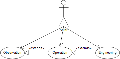
4.3 Use Cases
The following use cases illustrate the usage of the information model. Not all necessary Objects must be realized within a concrete OPC UA Server. These use cases cover a system that is BACnet client and OPC UA server. The use cases for the other direction (OPC UA client and BACnet server) are not covered in the current version and may be added in a future version.
Observation
Observation comprises reading and monitoring data such as present value, trend log and events of BACnet objects available in an existing BACnet network from a BACnet OPC UA Server.
The representation of BACnet internetworks, devices their objects and properties is consistent across BACnet OPC UA server products.
The BACnet OPC UA server may restrict the exposed information from a BACnet internetwork through configuration and/or user autorization.
Example 1: Enterprise integration (monitoring energy consumption, comparing trends)
Example 2: Multi domain integration (building automation with industrial automation)
Operation
Operation inherits the functionality of observation and extends it.
Operation comprises writing data such as set points, selecting mode of operation or acknowledge alarms through the BACnet OPC UA server.
Example 1: Enterprise integration (writing set points)
Example 2: Multi domain integration (building automation with industrial automation) (writing operation mode)
Engineering (Configuration / Maintenance)
Engineering inherits the functionality of operation and extends it.
Engineering comprises of configuring BACnet objects through a BACnet OPC UA Server like configuring modes of operation, enabling/disabling alarms and configuring schedules.
Example1: The properties of BACnet devices may be configured by OPC UA clients during the installation or engineering phase.
Example2: If room assignments or names change, the object representation may need to be updated accordingly. The OPC UA mapping model may be used to access and modify this information.
The following Figure 4 shows the use case diagram.