
9 Mapping of DataTypes
9.1 Primitive data types
9.1.1 LocationName
This DataType is a String that represents an arbitrary name given to a location. It can be used to return location denominations in a simple way, independent of complex coordinate structures.
Its representation in the AddressSpace is defined in Table 29.
| Attributes | Value |
| BrowseName | LocationName |
| Subtype of String defined in OPC 10000-5. | |
9.1.2 NmeaCoordinateString
This DataType is a String that represents a GPS coordinate as defined by NMEA 0183 v. 4.10.
Its representation in the AddressSpace is defined in Table 30.
| Attributes | Value |
| BrowseName | NmeaCoordinateString |
| Subtype of String defined in OPC 10000-5. | |
9.1.3 CodeTypeDataType
This DataType is a String that represents a code type used for an AutoID Identifier.
Its representation in the AddressSpace is defined in Table 31.
| Attributes | Value |
| BrowseName | CodeTypeDataType |
| Subtype of String defined in OPC 10000-5. | |
The values in the CodeTypeDataType are extensible by individual manufacturers, starting with "CUSTOM:”. Predefined values are defined in Table 32
| Code Type Value | ScanData Value field in union defined in 9.4.2 | Data Type | Description |
| "RAW:BYTES" | ByteString | ByteString | AutoID Device specific raw data |
| "RAW:STRING" | String | String | AutoID Device specific raw data to be interpreted as string |
| "EPC" | Epc | ScanDataEpc | EPC binary structure as defined in 9.3.6 |
| “UID” | ByteString | ByteString | AutoID Identifier according to ISO/IEC 18000-3 Mode 3, ISO/IEC 18000-63 and GS1 EPCglobal™. |
| “GS1” | ByteString | ByteString | Raw data containing application identifiers (AI) and data according to ISO/IEC 15418. In case of RFID bit 0x17 of PC is not set. PC contains no AFI. In case of barcode data start with macro 05 according ISO/IEC 15434. |
| “ASC” | ByteString | ByteString | Raw data containing data identifiers (DI) and data according to ISO/IEC 15418. In case of RFID bit 0x17 is set. PC contains AFI. In case of barcode data start with macro 06 according ISO/IEC 15434. |
| "URI" | String | String | URI, e.g. EPC string value according to "GS1 EPC Tag Data Standard 1.6" Example ScanData String value: "urn:epc:id:sgtin:0614141.112345.400" Also usable for other URIs |
| "CUSTOM:xxx" | ByteString String Custom | ByteString String BaseDataType | Any custom defined value ("xxx" is a AutoID Device specific substring of arbitrary length). |
Transponder as well as optical 2D-Codes are data carrier for information usually displayed in bits and bytes. But the contained information could be organized in a certain structure. How to do this in a norm conforming way is described in the standard ISO/IEC 15434 “Syntax for high capacity ADC Media” (ADC stands for Automatic Data Capture).
The two most prominent data structures in use are following the rules of GS1 and the ASC MH1. They are described in the standard ISO/IEC 15418 (Data Identifier and Application Identifier).
It is the purpose of these international standards to define the syntax for high capacity ADC media (such as transponder or 2D-Codes), in order to enable ADC users to utilize a single mapping utility, regardless of which high capacity ADC media is employed.
The interoperability of different data structures is achieved by the definition of a Message Header and a Format Header. While the Message Header defines the start and the end of the data contained, the Format Header indicates which data format is used.
Below two examples are shown for a GS1 and an ASC data format.
Example GS1
<Macro05>01312345123457GS1012345GS17101231
Interpretation by the Reader
]d1[)>RS05GS0134012345123457GS1012345GS17101231RSEOT
Example ASC MH 10
<Macro06>25PLEABCBQ3DGS1T234567GS14D101231
Interpretation by the Reader
]d1[)>RS06GS 25PLEABCBQ3DGS1T234567GS14D20101231RSEOT
For RFID the data structures are controlled by AFIs (lower 8 bits of PC) when ISO format is used according ISO/IEC 15961-2 and -3. Depending on the AFI different data compression methods may be used. Details are described for example in ISO 17363, 17364, 17365, 17366 and 17367.
9.2 Enumeration DataTypes
9.2.1 AutoIdOperationStatusEnumeration
This DataType is an enumeration that specifies the status for the AutoID operations like scan, read, write, lock or kill. Its values are defined in Table 33.
Not all status values are usable for all AutoID reader types. The table contains flags to indicate the expected status values for the different reader types.
| Name | Description | OCR | Opt. | RFID | RTLS |
| SUCCESS_0 | Successful operation | X | X | X | X |
| MISC_ERROR_TOTAL_1 | The operation has not been executed in total | X | |||
| MISC_ERROR_PARTIAL_2 | The operation has been executed only partial | X | |||
| PERMISSON_ERROR_3 | Password required | X | |||
| PASSWORD_ERROR_4 | Password is wrong | X | |||
| REGION_NOT_FOUND_ERROR_5 | Memory region not available for the actual tag | X | |||
| OP_NOT_POSSIBLE_ERROR_6 | Operation not supported by the actual tag | X | |||
| OUT_OF_RANGE_ERROR_7 | Addressed memory not available for the actual tag | X | |||
| NO_IDENTIFIER_8 | The operation cannot be executed because no tag or code was inside the range of the AutoID Device or the tag or code has been moved out of the range during execution | X | X | X | X |
| MULTIPLE_IDENTIFIERS_9 | Multiple tags or codes have been selected, but the command can only be used with a single tag or code | X | X | X | |
| READ_ERROR_10 | The tag or code exists and has a valid format, but there was a problem reading the data (e.g. still CRC error after maximum number of retries) | X | X | ||
| DECODING_ERROR_11 | The (optical) code or plain text has too many failures and cannot be detected | X | X | ||
| MATCH_ERROR_12 | The code doesn’t match the given target value | X | X | ||
| CODE_NOT_SUPPORTED_13 | The code format is not supported by the AutoID Device | X | |||
| WRITE_ERROR_14 | The tag exists, but there was a problem writing the data | X | |||
| NOT_SUPPORTED_BY_DEVICE_15 | The command or a parameter combination is not supported by the AutoID Device | X | X | X | X |
| NOT_SUPPORTED_BY_TAG_16 | The command or a parameter combination is not supported by the tag | X | |||
| DEVICE_NOT_READY_17 | The AutoID Device is in a state not ready to execute the command | X | X | X | X |
| INVALID_CONFIGURATION_18 | The AutoID Device configuration is not valid | X | X | X | |
| RF_COMMUNICATION_ERROR_19 | This error indicates that there is a general error in the communication between the transponder and the reader | X | X | ||
| DEVICE_FAULT_20 | The AutoID Device has a hardware fault | X | X | X | X |
| TAG_HAS_LOW_BATTERY_21 | The battery of the (active) tag is low | X | X |
Its representation in the AddressSpace is defined in Table 34.
| Attribute | Value | |||||
| BrowseName | AutoIdOperationStatusEnumeration | |||||
| IsAbstract | False | |||||
| References | NodeClass | BrowseName | DataType | TypeDefinition | Other | |
|---|---|---|---|---|---|---|
| Subtype of Enumeration defined in OPC 10000-5. | ||||||
| 0:HasProperty | Variable | 0:EnumValues | 0:EnumValueType [] | 0:PropertyType | ||
9.2.2 DeviceStatusEnumeration
This DataType is an enumeration that defines operational states of an AutoID Device. Its values are defined in Table 35.
| Name | Description |
| Idle_0 | The AutoID Device is operating normally and ready to accept commands like Scan or ScanStart method calls (whichever are supported). |
| Error_1 | The AutoID Device is not operating normally. An error condition has to be fixed before normal operation is possible. |
| Scanning_2 | The AutoID Device is operating normally and asynchronous scanning (via ScanStart or automatically) is active. It is AutoID Device dependent which method calls other than ScanStop will be accepted in this state. |
| Busy_3 | The AutoID Device is operating normally, but currently busy (e.g. by synchronous calls of other clients) and not able to accept commands like Scan or ScanStart method calls. This state normally is a temporary one. |
Its representation in the AddressSpace is defined in Table 36.
| Attribute | Value | |||||
| BrowseName | DeviceStatusEnumeration | |||||
| IsAbstract | False | |||||
| References | NodeClass | BrowseName | DataType | TypeDefinition | Other | |
|---|---|---|---|---|---|---|
| Subtype of Enumeration defined in OPC 10000-5. | ||||||
| 0:HasProperty | Variable | 0:EnumStrings | 0:LocalizedText [] | 0:PropertyType | ||
9.2.3 LocationTypeEnumeration
This DataType is an enumeration that defines the format of the location of an object returned by an RTLS device or system. Its values are defined in Table 37.
| Name | Description |
| NMEA_0 | An NMEA string representing a coordinate as defined in 9.1.2. |
| LOCAL_1 | A local coordinate as defined in 9.3.4 |
| WGS84_2 | A lat/lon/alt coordinate as defined in 9.3.16 |
| NAME_3 | A name for a location as defined in 9.1.1 |
Its representation in the AddressSpace is defined in Table 38.
| Attribute | Value | |||||
| BrowseName | LocationTypeEnumeration | |||||
| IsAbstract | False | |||||
| References | NodeClass | BrowseName | DataType | TypeDefinition | Other | |
|---|---|---|---|---|---|---|
| Subtype of Enumeration defined in OPC 10000-5. | ||||||
| 0:HasProperty | Variable | 0:EnumStrings | 0:LocalizedText [] | 0:PropertyType | ||
9.2.4 RfidLockOperationEnumeration
This DataType is an enumeration that defines the operational mode of the LockTag Method Its values are defined in Table 39.
| Name | Description |
| Lock_0 | Locks the memory area |
| Unlock_1 | Unlocks the memory area |
| PermanentLock_2 | Locks the memory area irreversible |
| PermanentUnlock_3 | Unlocks the memory area irreversible |
Its representation in the AddressSpace is defined in Table 40.
| Attribute | Value | |||||
| BrowseName | RfidLockOperationEnumeration | |||||
| IsAbstract | False | |||||
| References | NodeClass | BrowseName | DataType | TypeDefinition | Other | |
|---|---|---|---|---|---|---|
| Subtype of Enumeration defined in OPC 10000-5. | ||||||
| 0:HasProperty | Variable | 0:EnumStrings | 0:LocalizedText [] | 0:PropertyType | ||
9.2.5 RfidLockRegionEnumeration
This DataType is an enumeration that defines the memory region that a lock operation affects. Its values are defined in Table 41.
| Name | Description |
| Kill_0 | The kill password |
| Access_1 | The access password |
| EPC_2 | The UII/EPC bank (bank 01) |
| TID_3 | The TID bank (bank 10) |
| User_4 | The user memory bank (bank 11) |
Its representation in the AddressSpace is defined in Table 42.
| Attribute | Value | |||||
| BrowseName | RfidLockRegionEnumeration | |||||
| IsAbstract | False | |||||
| References | NodeClass | BrowseName | DataType | TypeDefinition | Other | |
|---|---|---|---|---|---|---|
| Subtype of Enumeration defined in OPC 10000-5. | ||||||
| 0:HasProperty | Variable | 0:EnumStrings | 0:LocalizedText [] | 0:PropertyType | ||
9.2.6 RfidPasswordTypeEnumeration
This DataType is an enumeration that defines the type of a password. Its values are defined in Table 43.
| Name | Description |
| Access_0 | Access password |
| Kill_1 | Kill password |
| Read_2 | Read password |
| Write_3 | Write password |
Its representation in the AddressSpace is defined in Table 44.
| Attribute | Value | |||||
| BrowseName | RfidPasswordTypeEnumeration | |||||
| IsAbstract | False | |||||
| References | NodeClass | BrowseName | DataType | TypeDefinition | Other | |
|---|---|---|---|---|---|---|
| Subtype of Enumeration defined in OPC 10000-5. | ||||||
| 0:HasProperty | Variable | 0:EnumStrings | 0:LocalizedText [] | 0:PropertyType | ||
9.3 OPC UA Structure DataTypes
9.3.1 General
The Stuctured DataTypes in this chapter are formally defined in two different table formats.
One table format has the columns Name, Type and Description for the definition of standard OPC UA structures where all structure elements are mandatory and must be transported between OPC UA Client and Server.
The second table format has the columns Name, Type, Optional and Description for the definition of OPC UA structures with optional structure elements.
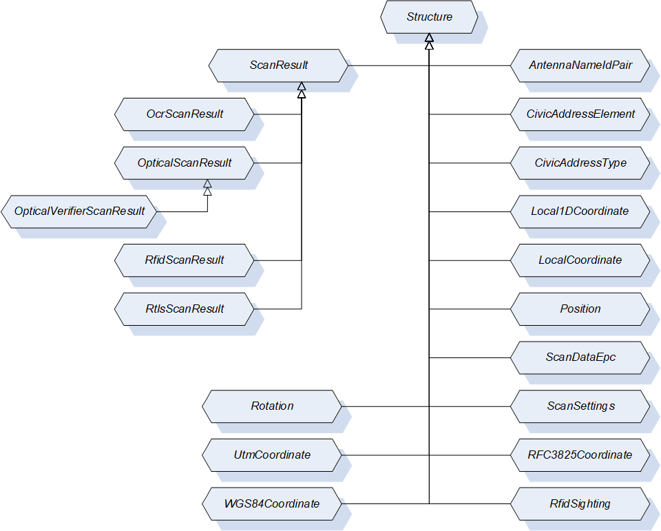
9.3.2 Structure DataType Overview
The following Figure 14 provides an overview of the Structure DataTypes defined for the AutoID Device access.
9.3.3 AntennaNameIdPair
This DataType is a structure that defines a pair of RFID antenna ID and antenna name. Its composition is formally defined in Table 45.
| Name | Type | Description |
| AntennaNameIdPair | Structure | Subtype of Structure defined in OPC 10000-5. |
AntennaId | Int32 | ID of the antenna returned in the RfidSighting contained in the RfidScanResult. The RfidSighting is defined in 9.3.13. The RfidScanResult is defined in 9.3.12. |
AntennaName | String | Name of the antenna with the AntennaId. |
Its representation in the AddressSpace is defined in Table 46.
| Attribute | Value | |||||
| BrowseName | AntennaNameIdPair | |||||
| IsAbstract | False | |||||
| References | NodeClass | BrowseName | DataType | TypeDefinition | Other | |
|---|---|---|---|---|---|---|
| Subtype of Structure defined in OPC 10000-5. | ||||||
9.3.4 LocalCoordinate
This DataType is a structure that defines the location of an object in a Cartesian local coordinate system arbitrarily chosen during configuration of an RTLS system. Its composition is formally defined in Table 47.
| Name | Type | Description |
| LocalCoordinate | Structure | Subtype of Structure defined in OPC 10000-5. |
| X | Double | The X – coordinate of the object’s position in the unit defined by the LengthUnit property of the AutoID Device. |
| Y | Double | The Y – coordinate of the object’s position in the unit defined by the LengthUnit property of the AutoID Device. |
| Z | Double | The Z – coordinate of the object’s position in the unit defined by the LengthUnit property of the AutoID Device. |
| Timestamp | UtcTime | Timestamp in UtcTime |
| DilutionOfPrecision | Double | DOP is a value for the variance of the measurements delivered by the location system. The calculation of the value depends on the underlying system and is vendor specific. Values should be in accordance with the implementations like in GNSS systems. |
| UsefulPrecision | Int32 | Values for Easting, Northing, and Altitude should be rounded by the clien tapplication to the n-th position after the decimal point. It specifies the number of useful digits after the decimal place. |
Its representation in the AddressSpace is defined in Table 48.
| Attribute | Value | |||||
| BrowseName | LocalCoordinate | |||||
| IsAbstract | False | |||||
| References | NodeClass | BrowseName | DataType | TypeDefinition | Other | |
|---|---|---|---|---|---|---|
| Subtype of Structure defined in OPC 10000-5. | ||||||
9.3.5 Position
This DataType is a structure that defines the position and the size of a code or a plain text within an image (so-called code area, used by OCR and optical code readers). Its composition is formally defined in Table 49.
| Name | Type | Description |
| Position | Structure | Subtype of Structure defined in OPC 10000-5. |
| PositionX | Int32 | X coordinate of the top-left edge of the code area (counting starts on the left side of the image) |
| PositionY | Int32 | Y coordinate of the top-left edge of the code area (counting starts on the top side of the image) |
| SizeX | Int32 | Horizontal size of the code area in pixel |
| SizeY | Int32 | Vertical size of the code area in pixel |
| Rotation | Int32 | The rotation of the code area |
Its representation in the AddressSpace is defined in Table 50.
| Attribute | Value | |||||
| BrowseName | Position | |||||
| IsAbstract | False | |||||
| References | NodeClass | BrowseName | DataType | TypeDefinition | Other | |
|---|---|---|---|---|---|---|
| Subtype of Structure defined in OPC 10000-5. | ||||||
9.3.6 ScanDataEpc
This DataType is a structure that defines the structure of the scanned data in Epc_1 format. Its composition is formally defined in Table 51.
| Name | Type | Description | Optional |
| ScanDataEpc | Structure | Subtype of Structure defined in OPC 10000-5. | |
PC | UInt16 | Protocol control information according to ISO/IEC 18000-3 Mode 3, ISO/IEC 18000-63 and GS1 EPCglobal™. | False |
UId | ByteString | AutoID Identifier according to ISO/IEC 18000-3 Mode 3, ISO/IEC 18000-63 and GS1 EPCglobal™. | False |
XPC_W1 | UInt16 | Extended protocol control word 1 according to ISO/IEC 18000-3 Mode 3, ISO/IEC 18000-63 and GS1 EPCglobal™. | True |
XPC_W2 | UInt16 | Extended protocol control word 2 according to ISO/IEC 18000-3 Mode 3, ISO/IEC 18000-63 and GS1 EPCglobal™. | True |
Its representation in the AddressSpace is defined in Table 52.
| Attribute | Value | |||||
| BrowseName | ScanDataEpc | |||||
| IsAbstract | False | |||||
| References | NodeClass | BrowseName | DataType | TypeDefinition | Other | |
|---|---|---|---|---|---|---|
| Subtype of Structure defined in OPC 10000-5. | ||||||
9.3.7 ScanSettings
This DataType is a structure that defines the settings for a scan execution. Its composition is formally defined in Table 53.
| Name | Type | Description | Optional |
| ScanSettings | Structure | Subtype of Structure defined in OPC 10000-5. | |
Duration | Duration | Duration of the scan operation in milliseconds. Duration is one of the termination conditions for the scan operation. The value 0 is infinite. The termination conditions are related to each other. If one of the conditions is fulfilled, the scan operation is stopped. | False |
Cycles | Int32 | Duration of the scan operation in ‘number of scan cycles’. The parameter Cycles is one of the termination conditions for the scan operation. The value 0 is infinite. The termination conditions are related to each other. If one of the conditions is fulfilled, the scan operation is stopped. | False |
DataAvailable | Boolean | If this value is set to True, the scan operation is completed as soon as scan data is available. If this value is set to False, only the other termination conditions are used. | False |
LocationType | LocationType Enumeration | The requestsd type of the location information returned in the scan results. The LocationTypeEnumeration DataType is defined in 9.2.3. | True |
Its representation in the AddressSpace is defined in Table 54.
| Attribute | Value | |||||
| BrowseName | ScanSettings | |||||
| IsAbstract | False | |||||
| References | NodeClass | BrowseName | DataType | TypeDefinition | Other | |
|---|---|---|---|---|---|---|
| Subtype of Structure defined in OPC 10000-5. | ||||||
9.3.8 ScanResult
This DataType is a structure that defines the results of a scan. Its composition is formally defined in Table 55.
| Name | Type | Description | Optional |
| ScanResult | Structure | Subtype of Structure defined in OPC 10000-5. | |
CodeType | CodeTypeDataType | Defines the format of the ScanData as string. The String DataType CodeTypeDataType and the predefined format strings are defined in 9.1.3. | False |
ScanData | ScanData | Holds the information about the detected objects e.g. the detected transponders. The ScanData DataType is defined in 9.4.2. | False |
Timestamp | UtcTime | Timestamp of the ScanResult creation. | False |
Location | Location | Returns the location of the object detection. The Location DataType is defined in 9.4.1. | True |
The ScanResult Structure representation in the AddressSpace is defined in Table 56.
| Attribute | Value | |||||
| BrowseName | ScanResult | |||||
| IsAbstract | True | |||||
| References | NodeClass | BrowseName | DataType | TypeDefinition | IsAbstract | |
|---|---|---|---|---|---|---|
| Subtype of Structure defined in OPC 10000-5. | ||||||
| Has Subtype | DataType | OcrScanResult | False | |||
| Has Subtype | DataType | OpticalScanResult | False | |||
| Has Subtype | DataType | RfidScanResult | False | |||
| Has Subtype | DataType | RtlsLocationResult | False | |||
9.3.9 OcrScanResult
This DataType is a structure that defines the results of an OCR reader device scan. Its composition is formally defined in Table 57.
| Name | Type | Description | Optional |
| OcrScanResult | Structure | Subtype of ScanResult defined in 9.3.8. | |
ImageId | NodeId | NodeId of the original scan image file object used for this scan result. This image file is also available through the Images folder defined in 6.2.3.2. | False |
Quality | Byte | Returns the probability of correct decoding. | False |
Position | Position | Returns the position of the text within the image The Position DataType is defined in 9.3.5. | False |
Font | String | Returns the font name used for decoding | True |
DecodingTime | UtcTime | Returns the required decoding time | True |
Its representation in the AddressSpace is defined in Table 58.
| Attribute | Value | |||||
| BrowseName | OcrScanResult | |||||
| IsAbstract | False | |||||
| References | NodeClass | BrowseName | DataType | TypeDefinition | Other | |
|---|---|---|---|---|---|---|
| Subtype of ScanResult defined in 9.3.8. | ||||||
9.3.10 OpticalScanResult
This DataType is a structure that defines the results of a scan. Its composition is formally defined in Table 59.
| Name | Type | Description | Optional |
| OpticalScanResult | Structure | Subtype of ScanResult defined in 9.3.8. | |
Grade | Float | Returns the Grade of the 1D/2D code according to IEC 15415 (2D) and IEC 15416 (1D). The Grade is a value between 0 and 4 where 0 is the worst quality and 4 is the best quality. | True |
Position | Position | Returns the position of the text within the image The Position DataType is defined in 9.3.5. | True |
Symbology | String | Type of barcode per ISO/IEC 15424. Example: "]I1". | True |
ImageId | NodeId | NodeId of the original scan image file object used for this scan result. | True |
Its representation in the AddressSpace is defined in Table 60.
| Attribute | Value | |||||
| BrowseName | OpticalScanResult | |||||
| IsAbstract | False | |||||
| References | NodeClass | BrowseName | DataType | TypeDefinition | IsAbstract | |
|---|---|---|---|---|---|---|
| Subtype of ScanResult defined in 9.3.8. | ||||||
| Has Subtype | DataType | OpticalVerifierScanResult | False | |||
9.3.11 OpticalVerifierScanResult
This DataType is a structure that defines the results of a scan. Its composition is formally defined in Table 61.
| Name | Type | Description | Optional |
| OpticalVerifierScanResult | Structure | Subtype of OpticalScanResult defined in 9.3.10. | |
IsoGrade | String | This value contains the ISO grade, the aperture and the wavelength used. Example content: "2.7/10/660" With the '2.7' being the grade, the '10' being the measuring aperture that was used for the analysis and the '660' is the wavelength of light used to illuminate the code. If the grade is reported without aperture and wavelength, then it really is quite meaningless (a code measured with an '06' aperture can give a totally different result that one measured with a '20' aperture for instance). | False |
RMin | Int16 | The minimum reflection value in percent (from a dark bar). Example: 6 | False |
SymbolContrast | Int16 | The Symbol Contrast value (Rmax – Rmin) in percent. Example: 41 | False |
ECMin | Int16 | The minimum Edge Contrast value in percent. Example: 31 | False |
Modulation | Int16 | The modulation (ECmin / SC) value in percent. Example: 76 | False |
Defects | Int16 | The defects value in percent. Example: 14 | False |
Decodability | Int16 | The decodability value in percent. Example: 87 | False |
Decode | Int16 | The decode content value in percent. Example: 100 | False |
PrintGain | Int16 | The print gain value in percent (-4%). Example: -4 | False |
Its representation in the AddressSpace is defined in Table 62.
| Attribute | Value | |||||
| BrowseName | OpticalVerifierScanResult | |||||
| IsAbstract | False | |||||
| References | NodeClass | BrowseName | DataType | TypeDefinition | Other | |
|---|---|---|---|---|---|---|
| Subtype of OpticalScanResult defined in 9.3.10. | ||||||
9.3.12 RfidScanResult
This DataType is a structure that defines the results of a RFID reader device scan. Its composition is formally defined in Table 63.
| Name | Type | Description |
| RfidScanResult | Structure | Subtype of ScanResult defined in 9.3.8. |
Sighting | RfidSighting [ ] | Returns additional information on the RFID-related properties of the scan event as array of RfidSightings. Each AutoID Identifier can be detected several times during a scan cycle. Each detection of the AutoID Identifier causes an entry into the Sightings array. The RfidSighting DataType is defined in 9.3.13. |
Its representation in the AddressSpace is defined in Table 64.
| Attribute | Value | |||||
| BrowseName | RfidScanResult | |||||
| IsAbstract | False | |||||
| References | NodeClass | BrowseName | DataType | TypeDefinition | Other | |
|---|---|---|---|---|---|---|
| Subtype of ScanResult defined in 9.3.8. | ||||||
9.3.13 RfidSighting
This DataType is a structure that defines additional RFID-related information of an AutoID Identifier detection during a scan cycle. Its composition is formally defined in Table 65.
| Name | Type | Description |
| RfidSighting | Structure | Subtype of Structure defined in OPC 10000-5. |
Antenna | Int32 | Returns the number of the antenna which detects the RFID tag first. |
Strength | Int32 | Returns the signal strength (RSSI) of the transponder. Higher values indicate a better strength. |
Timestamp | UtcTime | Timestamp in UtcTime. |
CurrentPowerLevel | Int32 | Returns the current power level (unit according to parameter settings) |
Its representation in the AddressSpace is defined in Table 66.
| Attribute | Value | |||||
| BrowseName | RfidSighting | |||||
| IsAbstract | False | |||||
| References | NodeClass | BrowseName | DataType | TypeDefinition | Other | |
|---|---|---|---|---|---|---|
| Subtype of Structure defined in OPC 10000-5. | ||||||
9.3.14 Rotation
This DataType is a structure that defines the rotation (or heading) of an object relative to the base coordinate system. The format is ‘yaw, pitch, roll’ as defined for aircraft principal axes. Its composition is formally defined in Table 67.
| Name | Type | Description |
| Rotation | Structure | Subtype of Structure defined in OPC 10000-5. |
Yaw | Double | The yaw of the object, in the unit defined for rotational measurements, e. g. in radians between PI and –PI (or in deg between +180° and -180°). Rotation measured around a vertical axis. Reference (yaw = 0) is the X-axis of the coordinate system |
Pitch | Double | The pitch of the object, in the unit defined for rotational measurements, e. g. in radians between PI and –PI (or in deg between +180° and -180°). Rotation measured around a horizontal axis. Reference (pitch = 0) is the direction of the yaw on the horizontal plane of the coordinate system |
Roll | Double | The roll of the object, in the unit defined for rotational measurements, e. g. in radians between PI and –PI (or in deg between +180° and -180°). Rotation measured around a horizontal axis pointing in the direction defined by yaw, pitch |
Its representation in the AddressSpace is defined in Table 68.
| Attribute | Value | |||||
| BrowseName | Rotation | |||||
| IsAbstract | False | |||||
| References | NodeClass | BrowseName | DataType | TypeDefinition | Other | |
|---|---|---|---|---|---|---|
| Subtype of Structure defined in OPC 10000-5. | ||||||
9.3.15 RtlsLocationResult
This DataType is a structure that defines the results that an RTLS device or system returns. It extends the ScanResult structure. Its composition is formally defined in Table 69.
The optional Location field defined in the ScanResult structure shall be included in RtlsLocationResults.
| Name | Type | Description | Optional |
| RtlsLocationResult | Structure | Subtype of ScanResult defined in 9.3.8. | |
Speed | Double | The current speed above ground of the located object. The unit is defined by the SpeedUnit variable. | True |
Heading | Double | The (geographical) direction the located object is moving in on a plane. The unit is defined by the RotationUnit variable, but note that the heading can be different from the rotation of the object. | True |
Rotation | Rotation | The rotation of the object identified by the UId as defined in 9.3.14. | True |
ReceiveTime | UtcTime | ReceiveTime provides the time the RTLS received the location information from the underlying device. | True |
Its representation in the AddressSpace is defined in Table 70.
| Attribute | Value | |||||
| BrowseName | RtlsLocationResult | |||||
| IsAbstract | False | |||||
| References | NodeClass | BrowseName | DataType | TypeDefinition | Other | |
|---|---|---|---|---|---|---|
| Subtype of ScanResult defined in 9.3.8. | ||||||
9.3.16 WGS84Coordinate
This DataType is a structure that defines the georeferenced location of an object on the earth’s surface in latitude, longitude and altitude using the World Geodetic System’s (WGS84) reference frame. Its composition is formally defined in Table 71.
| Name | Type | Description |
| WGS84Coordinate | Structure | Subtype of Structure defined in OPC 10000-5. |
N/S Hemisphere | String | ‘N’ or ‘S’ for northern or southern hemisphere |
Latitude | Double | Latitude in the unit defined by the GeographicalUnit property of the DeviceLocation Variable of the AutoID Device defined in 6.1.3.12. |
E/W Hemisphere | String | ‘E’ or ‘W’ for eastern or western hemisphere |
Longitude | Double | Longitude in the unit by the GeographicalUnit property of the DeviceLocation Variable of the AutoID Device defined in 6.1.3.12. |
Altitude | Double | Altitude in the unit by the GeographicalUnit property of the DeviceLocation Variable of the AutoID Device defined in 6.1.3.12. |
Timestamp | UtcTime | Timestamp in UtcTime |
DilutionOfPrecision | Double | DOP is a value for the variance of the measurements delivered by the location system. The calculation of the value depends on the underlying system and is vendor specific. Values should be in accordance with the implementations like in GNSS systems. |
UsefulPrecisionLatLon | Int32 | Values for Latitude and Longitude should be rounded by the client application to the n-th position after the decimal point. It specifies the number of useful digits after the decimal place. |
UsefulPrecisionAlt | Int32 | Values for Altitude should be rounded by the client application to the n-th position after the decimal point. It specifies the number of useful digits after the decimal place. |
Its representation in the AddressSpace is defined in Table 72.
| Attribute | Value | |||||
| BrowseName | WGS84Coordinate | |||||
| IsAbstract | False | |||||
| References | NodeClass | BrowseName | DataType | TypeDefinition | Other | |
|---|---|---|---|---|---|---|
| Subtype of Structure defined in OPC 10000-5. | ||||||
9.3.17 AccessResult
This DataType is a structure that defines the result values of an AutoID Identifier access of an AutoID device. Its composition is formally defined in Table 73.
| Name | Type | Description | Optional |
| AccessResult | Structure | Subtype of Structure defined in OPC 10000-5. | |
CodeType | CodeTypeDataType | Defines the format of Identifier as string. The String DataType CodeTypeDataType and the predefined format strings are defined in 9.1.3. | true |
Identifier | ScanData | The AutoID identifier (e.g. a code or a transponder) which was accessed by the command. The ScanData DataType is defined in 9.4.2. When this value exists, the value CodeType must be available too. | true |
Timestamp | UtcTime | The point of time the AutoID Identifier was accessed by the command. | true |
The AccessResult Structure representation in the AddressSpace is defined in Table 74.
| Attribute | Value | |||||
| BrowseName | AccessResult | |||||
| IsAbstract | False | |||||
| References | NodeClass | BrowseName | DataType | TypeDefinition | IsAbstract | |
|---|---|---|---|---|---|---|
| Subtype of Structure defined in OPC 10000-5. | ||||||
| Has Subtype | DataType | RfidAccessResult | False | |||
9.3.18 RfidAccessResult
This DataType is a structure that defines the additional result values of a Rfid Transponder access of a Rfid reader device. Its composition is formally defined in Table 75.
| Name | Type | Description | Optional |
| RfidAccessResult | Structure | Subtype of AccessResult defined in 9.3.17. | |
CodeTypeRWData | CodeTypeDataType | Defines the format of RWData as string. The String DataType CodeTypeDataType and the predefined format strings are defined in 9.1.3. | true |
RWData | ScanData | The user data which was written to / was read from the Rfid Transponder by the command. The ScanData DataType is defined in 9.4.2. When this value exists, the value CodeType must be available too. | true |
Antenna | Int32 | The antenna by which the transponder was accessed by the command. | true |
CurrentPowerLevel | Int32 | The power level with which the transponder was accessed by the command. | true |
PC | UInt16 | The Protocol Control Word of the transponder accessed by the command. | true |
Polarization | String | The Polarization with which the transponder was accessed by the command. | true |
Strength | Int32 | The Rssi value with which the transponder was accessed by the command. | true |
Its representation in the AddressSpace is defined in Table 76.
| Attribute | Value | |||||
| BrowseName | RfidAccessResult | |||||
| IsAbstract | False | |||||
| References | NodeClass | BrowseName | DataType | TypeDefinition | Other | |
|---|---|---|---|---|---|---|
| Subtype of AccessResult defined in 9.3.17. | ||||||
9.4 OPC UA Union DataTypes
9.4.1 Location
This DataType is a union that defines different types of location values. Its composition is formally defined in Table 77.
| Name | Type | Description |
| Location | Union | |
NMEA | NmeaCoordinateString | The DataType NmeaCoordinateString is defined in 9.1.2. |
Local | LocalCoordinate | The DataType LocalCoordinate is defined in 9.3.4. |
WGS84 | WGS84Coordinate | The DataType WGS84Coordinate is defined in 9.3.16. |
Name | LocationName | The DataType LocationName is defined in 9.1.1 |
Its representation in the AddressSpace is defined in Table 78.
| Attribute | Value | |||||
| BrowseName | Location | |||||
| IsAbstract | False | |||||
| References | NodeClass | BrowseName | DataType | TypeDefinition | Other | |
|---|---|---|---|---|---|---|
| Subtype of Union defined in OPC 10000-5. | ||||||
9.4.2 ScanData
This DataType is a union that defines the format of the data scanned by the AutoID Device. Its composition is formally defined in Table 79.
| Name | Type | Description |
| ScanData | Union | |
ByteString | ByteString | Scanned data in RAW format. |
String | String | Scanned data as String. |
Epc | ScanDataEpc | Scanned data as ScanDataEpc structure. |
Custom | BaseDataType | Vendor specific data structure. |
Its representation in the AddressSpace is defined in Table 80.
| Attribute | Value | |||||
| BrowseName | ScanData | |||||
| IsAbstract | False | |||||
| References | NodeClass | BrowseName | DataType | TypeDefinition | Other | |
|---|---|---|---|---|---|---|
| Subtype of Union defined in OPC 10000-5. | ||||||