AutomationML models are divided into different hierarchical trees (see Figure 7): InstanceHierarchy, RoleClassLibs, SystemUnitClassLib, and InterfaceClassLib.
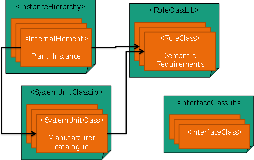
Figure 7 – AutomationML hierarchical trees
The main AutomationML elements and all possible relations between them are shown in Figure 8. The organization in a hierarchical tree involves that every element type can have child elements of the same type (see ChildElement relations). SystemUnitClasses and RoleClasses are defined in an inheritance structure; the RefBaseClassPath relations define such inheritance relations. RoleClasses can be assigned to SystemUnitClasses and InternalElements. In the latter case there are two different ways to make the RoleClass assignment using SupportedRoleClasses or the RoleRequirement. The remaining arrows in Figure 8 describe the possible relations between InternalElements and SystemUnitClasses. An InternalElement can inherit from a SystemUnitClass. In the scope of AutomationML SystemUnitClasses are only templates and can be changed after instantiation. The backward relation indicates that a SystemUnitClass can define sub-elements in terms of InternalElements. These sub-elements (InternalElements) should be included on instantiation. RoleClasses describe functions of a physical or logical plant object independent of a technical implementation. They offer a possibility to specify an object in an abstract way and independent of the manufacturer. The assignment of a RoleClass to an object (SystemUnitClass or InternalElement) results in the allocation of fundamental functions or requirements.
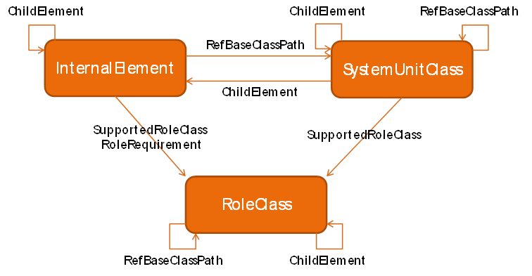
Figure 8 – AutomationML main elements
Figure 9 depicts the basic structure of a RoleClass (RC), SystemUnitClass (SUC), or InternalElement (IE). Each can contain arbitrary nested Attributes and Interfaces (see ChildElement relations). The Interfaces are called ExternalInterfaces and shall inherit from an InterfaceClass. They can be connected to other ExternalElements via InternalLinks. The InterfaceClasses are stored hierarchically and shall have independent inheritance relations. InterfaceClasses and certainly ExternalInterfaces may also have arbitrary nested Attributes.
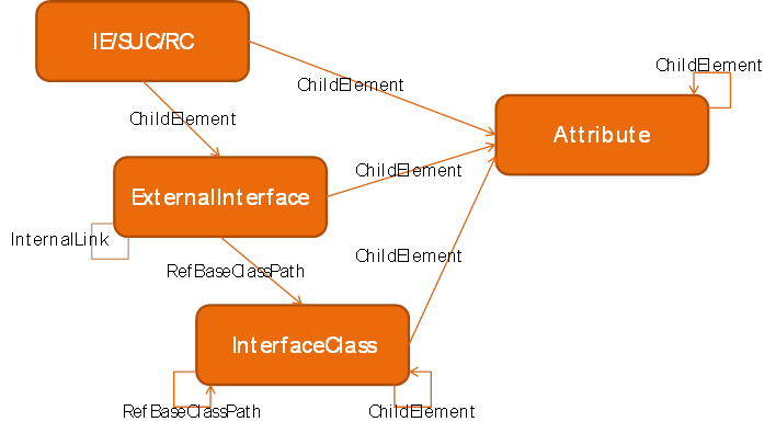
Figure 9 – AutomationML main object details.
Several nodesets (see Figure 10) are defined to organise the address space. Figure 10 includes the nodeset name, the corresponding namespace URI and the file name containing the nodeset. All nodesets are based on the UA Base types. The nodeset AutomationML Base types (AML, see Chapter 6) defines all nodes and type definitions necessary for the modelling of AutomationML in OPC UA. This includes e.g. organisational nodes for the entry into the AutomationML folder for RoleClassLibs or AutomationML types (ObjectType CAEXFileType). One nodeset is defined for the standardised and informative AutomationML libraries (AMLLibs, see Chapter 6.4) coming from IEC62714-1, IEC62714-2, IEC62714-3, and IEC62714-4. And finally, one or more nodesets are used for the concrete AutomationML documents (Filename of each AutomationML document).
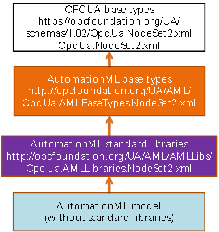
Figure 10 – Different nodesets for the usage of AutomationML in OPC UA information models
The main structure of an AutomationML file from Figure 7 is mapped into a slightly variant structure depicted in Figure 11. The InstanceHierarchies and libraries shall be stored in common folders (AutomationMLInstanceHierarchies, AutomationMLLibraries, AutomationMLSystemUnitClassLibs, AutomationMLRoleClassLibs, AutomationMLInterfaceClassLibs).
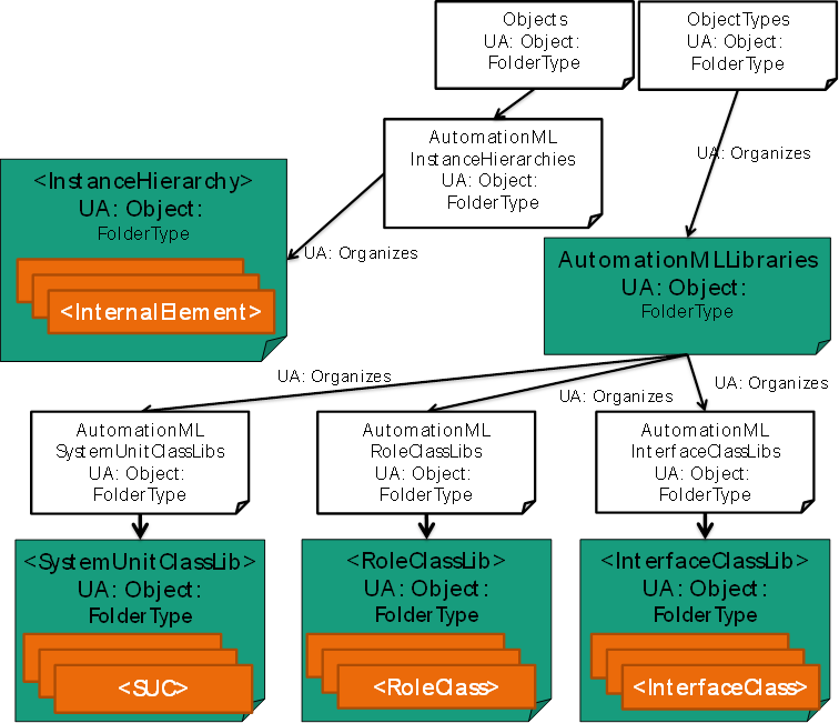
Figure 11 – CAEX file <-> OPC UA Types [1]
The AutomationML BaseElementTypes transformation into OPC UA Types is depicted in Figure 12, the transformation of AutomationML elements into OPC UA Types is depicted in Figure 13.
Figure 12 depicts the mapping of the relations between the main AutomationML elements (see Figure 8). The structure of the picture is not changed, so the mapping can be read directly from the graphic. Table 7 and Table 8 resume the mapping rules in a list. Basically, AutomationML InternalElements are represented by OPC UA Objects, AutomationML SystemUnitClasses and RoleClasses are represented by OPC UA ObjectTypes. Detailed definition of new ObjectTypes, ReferenceTypes and VariableTypes are given in Chapter 6.
ChildElement relations within class structures (SystemUnitClass, RoleClass) are mapped to the OPC UA ‘Organizes’ references. InternalElements which follow the ChildElement relation are referenced via ‘HasComponent’ references. The inheritance relations within SystemUnitClasses and RoleClasses are mapped to OPC UA ‘HasSubtype’ references. The internal structures of SystemUnitClasses are depicted by InternalElements which are connected via OPC UA ‘HasComponent’ references. The RefBaseClassPath relation of AutomationML is an OPC UA ‘HasTypeDefinition’ reference. The referencing of RoleClasses to InternalElements or SystemUnitClasses via SupportedRoleClass or RoleRequirement of AutomationML is done via OPC UA ‘HasAMLRoleReference’ references.
|
AutomationML |
OPC UA |
|
InternalElement |
Object |
|
SystemUnitClass |
ObjectType |
|
RoleClass |
ObjectType |
|
AutomationML Source |
AutomationML Target |
AutomationML Relation |
OPC UA Reference |
Description |
|
InternalElement |
RoleClass |
SupportedRoleClass |
HasAMLRoleReference |
Semantic similar to HasTypeDefinition |
|
InternalElement |
RoleClass |
RoleRequirement |
HasAMLRoleReference |
Semantic similar to HasTypeDefinition |
|
InternalElement |
SystemUnitClass |
RefBaseClassPath |
HasTypeDefinition |
|
|
InternalElement |
InternalElement |
|
HasComponent |
ChildElement |
|
SystemUnitClass |
RoleClass |
SupportedRoleClass |
HasAMLRoleReference |
Semantic similar to HasTypeDefinition |
|
SystemUnitClass |
InternalElement |
|
HasComponent |
ChildElement |
|
SystemUnitClass |
SystemUnitClass |
|
Organizes |
ChildElement |
|
SystemUnitClass |
SystemUnitClass |
RefBaseClassPath |
HasSubtype |
|
|
RoleClass |
RoleClass |
|
Organizes |
ChildElement |
|
RoleClass |
RoleClass |
RefBaseClassPath |
HasSubtype |
|
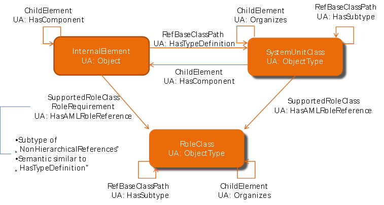
Figure 12 – AutomationML BaseElementTypes and the OPC UA Types [1]
The mappings of the AutomationML object details (see Figure 9) are depicted in Figure 13. The analogy between the two figures is obvious. Table 9 and Table 10 summarize the mapping rules in a list. AutomationML Attributes become OPC UA Variables. AutomationML InterfaceClasses are transformed into OPC UA ObjectTypes and the corresponding AutomationML ExternalInterface elements are modelled by OPC UA Objects.
The Attributes and ExternalInterfaces are referenced via ‘HasComponent’ references. The InterfaceClass is the type definition of the ExternalInterface therefore it is assigned via ‘HasTypeDefinition’ reference. Similarly to the RoleClasses and SystemUnitClasses, the relations between InterfaceClasses are mapped to ‘Organizes’ references within the XML tree structure and to ‘HasSubtype’ references concerning inheritance relation. Relations between ExternalInterfaces (AutomationML InternalLinks) are assigned via ‘HasAMLInternalLink’ reference. Details are given in Chapter 6.
|
AutomationML |
OPC UA |
|
InternalElement |
Object |
|
SystemUnitClass |
ObjectType |
|
RoleClass |
ObjectType |
|
InterfaceClass |
ObjectType |
|
Attribute |
Variable |
|
ExternalInterface |
Object |
|
AutomationML Source |
AutomationML Target |
AutomationML Relation |
OPC UA Reference |
Description |
|
InternalElement |
Attribute |
|
HasComponent |
ChildElement |
|
SystemUnitClass |
Attribute |
|
HasComponent |
ChildElement |
|
RoleClass |
Attribute |
|
HasComponent |
ChildElement |
|
InternalElement |
ExternalInterface |
|
HasComponent |
ChildElement |
|
SystemUnitClass |
ExternalInterface |
|
HasComponent |
ChildElement |
|
RoleClass |
ExternalInterface |
|
HasComponent |
ChildElement |
|
ExternalInterface |
ExternalInterface |
InternalLink |
HasAMLInternalLink |
|
|
ExternalInterface |
Attribute |
|
HasComponent |
ChildElement |
|
ExternalInterface |
InterfaceClass |
RefBaseClassPath |
HasTypeDefinition |
|
|
InterfaceClass |
Attribute |
|
HasComponent |
ChildElement |
|
InterfaceClass |
InterfaceClass |
RefBaseClassPath |
HasSubtype |
|
|
InterfaceClass |
InterfaceClass |
|
Organizes |
ChildElement |
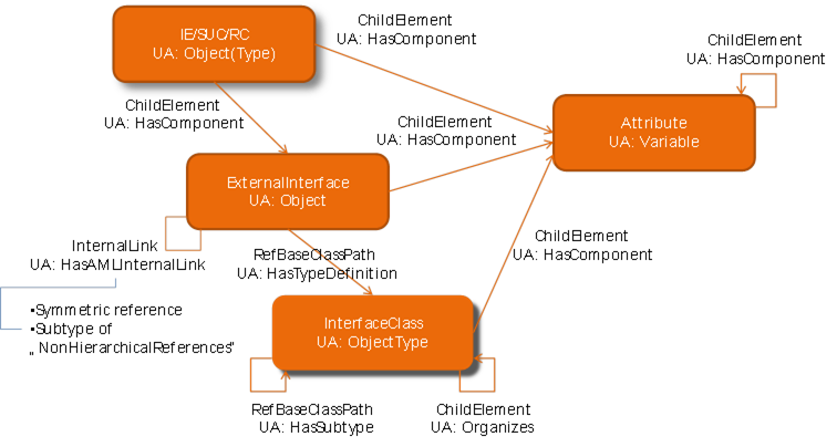
Figure 13 – AutomationML Element and the OPC UA Types [1]
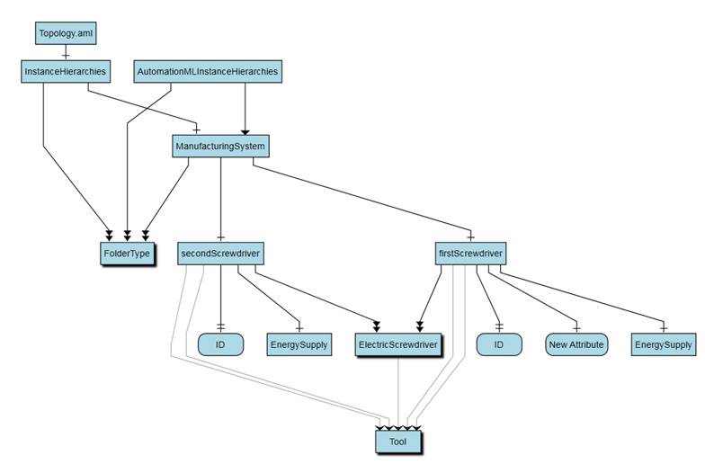
Figure 14 depicts the tree structure of an AutomationML example. This example shows a simple AutomationML document (version 2.0) which contains:
- one InstanceHierarchy with InternalElements
- one SystemUnitClassLib with one SystemUnitClass
- one RoleClassLib with one RoleClass and
- one InterfaceClassLib with one InterfaceClass.
The elements in this example are designed to model some aspects of a manufacturing system. The RoleClassLib contains a RoleClass to characterize a system component as a ’Tool’. The InterfaceClassLib contains an InterfaceClass which models the energy supply of any tool. The SystemUnitClassLib contains a class representing an electric screwdriver. The InstanceHierarchy describes a manufacturing system containing the two screwdrivers in the system.
The used AutomationML-Libraries (AutomationMLBaseRoleClassLibrary and AutomationMLInterfaceClassLibrary) are stored in separated CAEX files and are included via external references.
Annex A contains the XML text of the example in AutomationML.
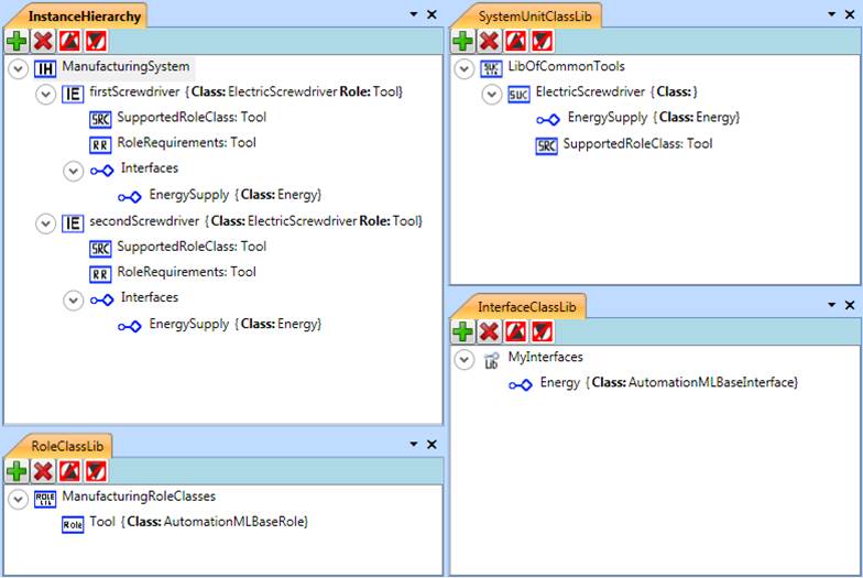
Figure 14 – AutomationML example.
The example shown in Figure 14 will now be redefined within OPC UA. Annex A contains the XML text of the example in OPC UA.
Figure 15 depicts the main structure of the example including the folder objects for the organization of the address space. The used graphical notation is defined by the OPC Foundation and is explained in chapter 4.2.2. It includes the OPC UA Objects used to organize the address space structure which are explained in chapter 6.4.1.
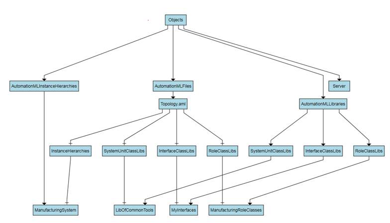
Figure 15 – Example main structure in OPC UA.
Figure 16 depicts the role classes of the example. It includes the inheritance structure of the roles. In the RoleClassLibs ‘ManufacturingRoleClasses’ the RoleClass ‘Tool’ is included.
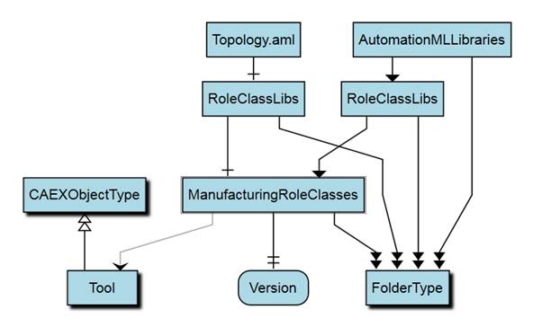
Figure 16 – Example role classes in OPC UA.
Figure 17 shows the SystemUnitClasses. The SystemUnitClassLib ‘LibOfCommonTools’ includes a SystemUnitClass ‘ElectricScrewdriver’ with reference to the role ‘Tool’. This SystemUnitClass includes an ExternalInterface ‘EnergySupply’.
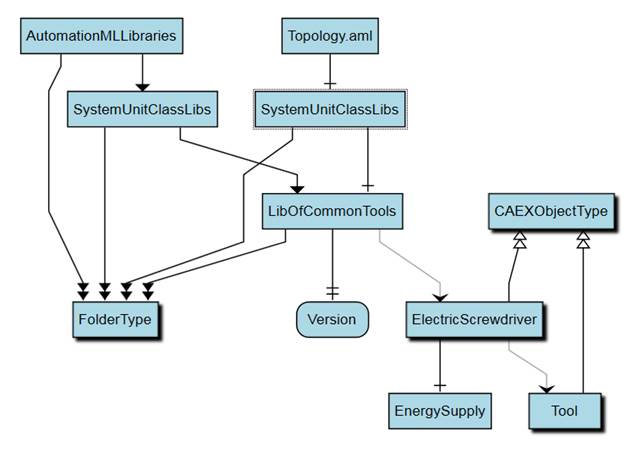
Figure 17 – Example system unit classes in OPC UA.
In Figure 18 you can find the InterfaceClassLib ‘MyInterfaces’ including the InterfaceClass ‘Energy’.
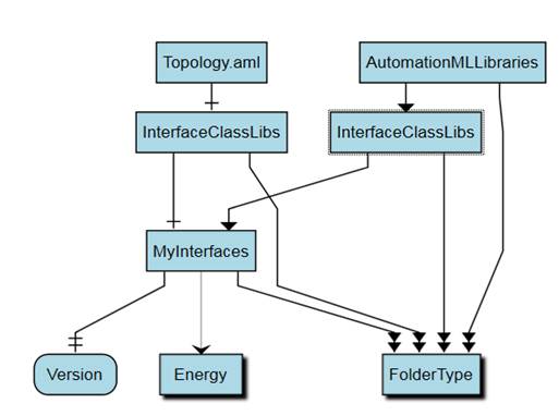
Figure 18 – Example interface classes in OPC UA.
The mapping of the InstanceHierarchy is shown in Figure 19. The File ‘Topology.aml’ includes the InstanceHierarchy ‘ManufacturingSystem’ which includes two InternalElements ‘firstScrewdriver’ and ‘secondScrewdriver’. They are derived from the SystemUnitClass ‘ElectricScrewdriver’ and inherit its structure and elements, such as a variable ‘ID’, an ExternalInterface ‘EnergySupply’ and the assigned RoleClass ‘Tool’. The InternalElement ‘firstScrewdriver’ additionally consists of a variable ‘NewAttribute’.