
4 General information to AutomationML and OPC UA
4.1 Introduction to AutomationML
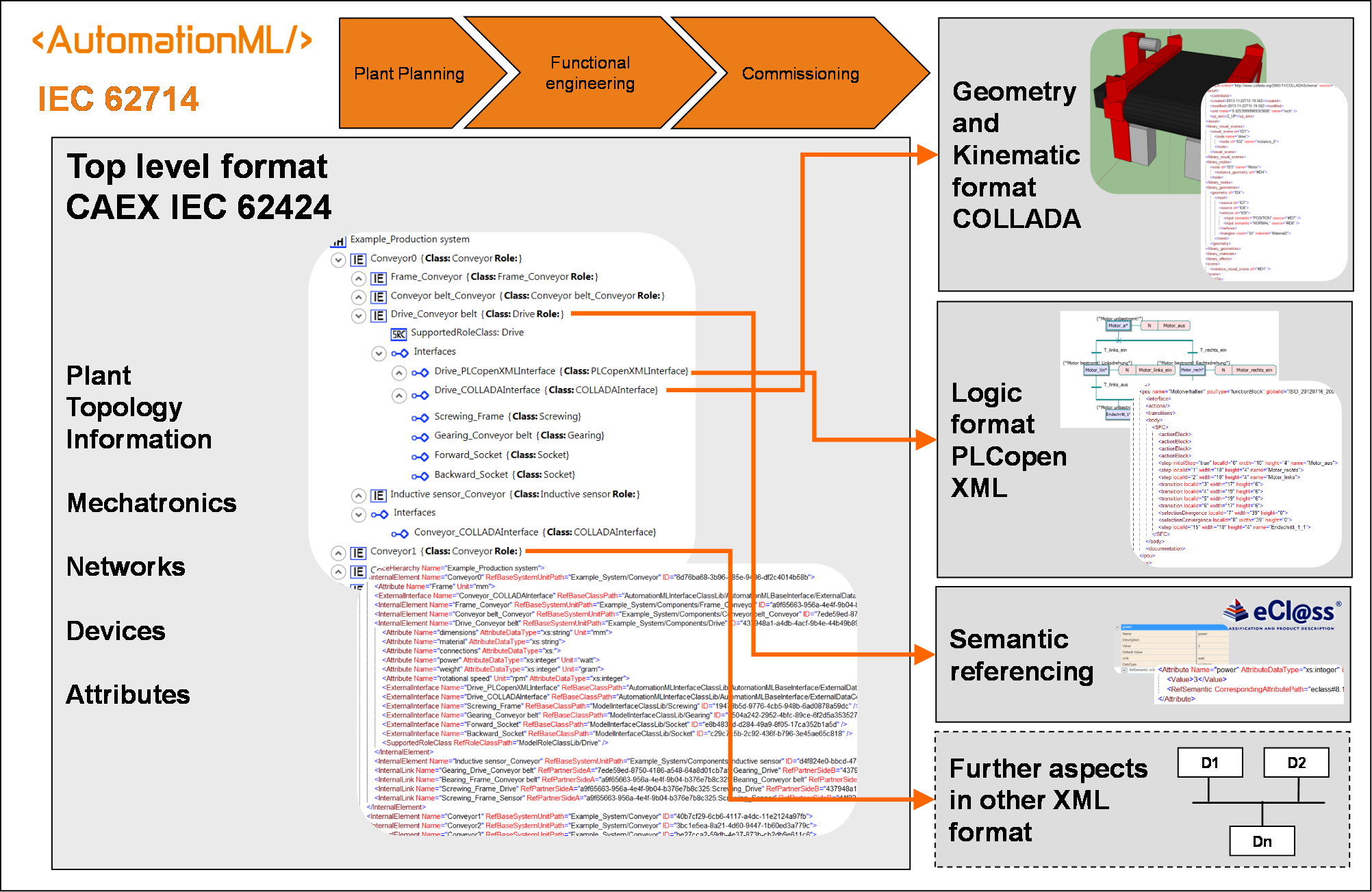
The AutomationML data format, developed by AutomationML e.V., standardised in IEC 62714, is an open, neutral, XML-based, and free data exchange format which enables a domain and company spanning transfer of engineering data of production systems in a heterogeneous engineering tool landscape. The goal of AutomationML is to interconnect engineering tools in their different disciplines, e.g. plant planning, mechanical engineering, electrical engineering, process engineering, process control engineering, HMI development, PLC programming, robot programming.
AutomationML stores engineering information following the object oriented paradigm and allows modelling of physical and logical plant components as data objects encapsulating different aspects. An object may consist of other sub-objects, and may itself be part of a larger composition or aggregation. Typical objects in plant automation comprise information on topology, geometry, kinematics, logic, and behaviour.
In addition, AutomationML follows a modular structure. AutomationML is based on IEC 62424 (CAEX) and integrates other already existing XML-based data formats (see Figure 1). These data formats are used on an “as-is” basis within their own specifications and are not branched for AutomationML needs.
Logically AutomationML is partitioned in:
description of the plant structure and communication systems expressed as a hierarchy of AutomationML objects and described by means of CAEX following IEC 62424
description of geometry and kinematics of the different AutomationML objects represented by means of COLLADA 1.4.1 and 1.5.0 (ISO/PAS 17506:2012)
description of control related logic data of the different AutomationML objects represented by means of PLCopen XML 2.0 and 2.0.1 (IEC61131-10)
description of relations among AutomationML objects and references to information that is stored in documents outside the top level format
Due to the different aspects of AutomationML, the IEC 62714 series consists of different parts focussing on different aspects:
IEC 62714-1: Architecture and general requirements - This part specifies the general AutomationML architecture, the modelling of engineering data, classes, instances, relations, references, hierarchies, basic AutomationML libraries and extended AutomationML concepts. It describes the use of CAEX. It is the basis of all future parts and provides mechanisms to reference other sub-formats.
IEC 62714-2: Role class libraries - This part is intended to specify additional AutomationML libraries to derive necessary roles for semantic definition in individual application cases.
IEC 62714-3: Geometry and kinematics - This part is intended to specify the modelling of geometry and kinematics information based on COLLADA.
IEC 62714-4: Logic - This part is intended to specify the modelling of logics, sequencing, behaviour and control related information based on PLCopen XML.
Further parts may be added in the future in order to interconnect additional data standards to AutomationML.
4.1.1 Top-level format CAEX
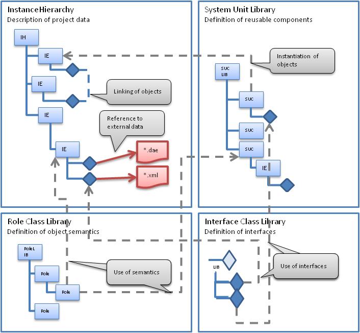
The foundation of AutomationML is the application of CAEX as the top level format. Furthermore, AutomationML defines an appropriate CAEX profile fulfilling all relevant needs of AutomationML to model engineering information of production systems. It integrates the three data formats CAEX, COLLADA, and PLCopenXML, and enables an extension, if necessary, in the future.
CAEX enables an object oriented approach (see Figure 2) where
semantics of system objects can be specified using roles defined and collected in role class libraries,
semantics of interfaces between system objects can be specified using interface classes defined and collected in interface class libraries,
classes of system objects can be specified using system unit classes (SUC) defined and collected in system unit class libraries, and
individual objects are modelled in an instance hierarchy (IH) as a hierarchy of internal elements (IE) referencing system unit classes they are derived from, role classes defining its semantics, and interface objects used to interlink objects among each other or with externally modelled information (e.g. COLLADA and PLCopenXML files).
4.2 Introduction to OPC Unified Architecture
4.2.1 General
The main use case for OPC standards is the online data exchange between devices and HMI or SCADA systems using Data Access functionality. In this use case the device data is provided by an OPC server and is consumed by an OPC client integrated into the HMI or SCADA system. OPC DA provides functionality to browse through a hierarchical namespaces containing data items and to read, write and to monitor these items for data changes. The classic OPC standards are based on Microsoft COM/DCOM technology for the communication between software components from different vendors. Therefore classic OPC server and clients are restricted to Windows PC based automation systems.
OPC UA incorporates all features of classic OPC standards like OPC DA, A&E and HDA but defines platform independent communication mechanisms and generic, extensible and object-oriented modelling capabilities for the information a system wants to expose.
The OPC UA network communication part defines different mechanisms optimized for different use cases. The first version of OPC UA is defining an optimized binary TCP protocol for high performance intranet communication as well as a mapping to accepted internet standards like Web Services. The abstract communication model does not depend on a specific protocol mapping and allows adding new protocols in the future. Features like security, access control and reliability are directly built into the transport mechanisms. Based on the platform independence of the protocols, OPC UA servers and clients can be directly integrated into devices and controllers.
The OPC UA Information Model provides a standard way for Servers to expose Objects to Clients. Objects in OPC UA terms are composed of other Objects, Variables and Methods. OPC UA also allows relationships to other Objects to be expressed.
The set of Objects and related information that an OPC UA Server makes available to Clients is referred to as its AddressSpace. The elements of the OPC UA Object Model are represented in the AddressSpace as a set of Nodes described by Attributes and interconnected by References. OPC UA defines eight classes of Nodes to represent AddressSpace components. The classes are Object, Variable, Method, ObjectType, DataType, ReferenceType and View. Each NodeClass has a defined set of Attributes.
This specification makes use of three essential OPC UA NodeClasses: Objects, Methods and Variables.
Objects are used to represent components of a system. An Object is associated to a corresponding ObjectType that provides definitions for that Object.
Methods are used to represent commands or services of a system.
Variables are used to represent values. Two categories of Variables are defined, Properties and DataVariables.
Properties are Server-defined characteristics of Objects, DataVariables and other Nodes. Properties are not allowed to have Properties defined for them. An example for Properties of Objects is the Object_Identifier Property of a XXX ObjectType.
DataVariables represent the contents of an Object. DataVariables may have component DataVariables. This is typically used by Servers to expose individual elements of arrays and structures. This specification uses DataVariables to represent data like the XXX of a XXX Object.
4.2.2 Graphical Notation
OPC UA defines a graphical notation for an OPC UA AddressSpace. It defines graphical symbols for all NodeClasses and how different types of References between Nodes can be visualized. Figure 3 shows the symbols for the six NodeClasses used in this specification. NodeClasses representing types always have a shadow.
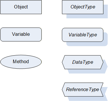
Figure 4 shows the symbols for the ReferenceTypes used in this specification. The Reference symbol is normally pointing from the source Node to the target Node. The only exception is the HasSubType Reference. The most important References like HasComponent, HasProperty, HasTypeDefinition and HasSubType have special symbols avoiding the name of the Reference. For other ReferenceTypes or derived ReferenceTypes the name of the ReferenceType is used together with the symbol.
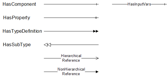
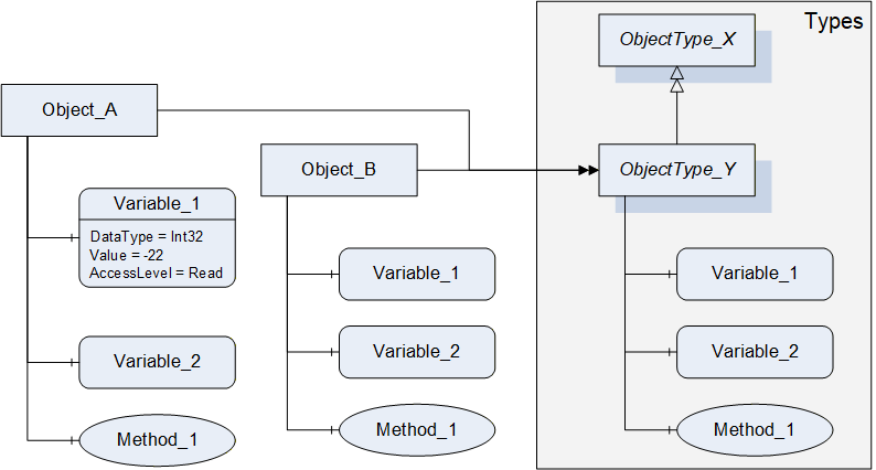
Figure 5 shows a typical example for the use of the graphical notation. Object_A and Object_B are instances of the ObjectType_Y indicated by the HasTypeDefinition References. The ObjectType_Y is derived from ObjectType_X indicated by the HasSubType Reference. The Object_A has the components Variable_1, Variable_2 and Method_1.
To describe the components of an Object on the ObjectType the same NodeClasses and References are used on the Object and on the ObjectType like for ObjectType_Y in the example. The instance Nodes used to describe an ObjectType are instance declaration Nodes.
To provide more detailed information for a Node, a subset or all Attributes and their values can be added to a graphical symbol.
4.3 Use Cases
The specification describes the combination of AutomationML with OPC UA online information like process data and diagnostic information. It extends the application domain of OPC UA (see Figure 6). Therefore, different use cases which will be possible by the combination of both standards were identified.
One opportunity from combining AutomationML and OPC UA is to communicate and operationalise AutomationML by means of OPC UA. It is possible to simplify the creation of OPC UA information models based on existing AutomationML data. This can be realized by a so called OPC UA companion specification due to analogies between AutomationML and the OPC UA information model. The companion specification for AutomationML consists of an object model including many specific semantics which can be used online with multiple involved parties by OPC UA. This makes an online version of the AutomationML model possible - AutomationML models can be exchanged via OPC UA – and includes OPC UA data management, online communication functionality, multi-user support, access methods, security, etc. This is especially important for re-engineering and maintenance use cases where the AutomationML model evolves over time. The present AutomationML model can be managed by OPC UA and makes an up-to-date description of the system as-is possible.
One other opportunity is the lossless exchange of the OPC UA system configuration within AutomationML models. The manual exchange of OPC UA server configuration data will be replaced by a specified description in AutomationML. Parameters to set up OPC UA communication between tools can be exchanged using AutomationML. This realizes consistent data, produces less errors and results in an easier and faster configuration of UA servers and clients. OPC UA can benefit from the description of the complete communication network configuration and structure including communication components of sensors and actuators with respect to communication system parameters, network structure and wiring, quality of service.