The object model that describes analysers is separated into a definition of AnalyserDevice, AnalyserChannel, Stream, Accessory and AccessorySlot.
Figure 1 provides a high-level view of how those components are related to each other. In general terms AnalyserDevice represents the instrument as a whole. Each AnalyserDevice has at least one AnalyserChannel and may have AccessorySlots through which an Accessory can be connected. Similarly, each AnalyserChannel may have AccessorySlots through which Accessories can be connected. Data acquisition occurs through the AnalyserChannel or through the Accessory connected to that AnalyserChannel. Accessories can only be connected through the AccessorySlots.
The interface with the process to monitor is done through a sampling system that connects the AnalyserChannel to a specific sampling point in the process. This connection is also referred as a Stream.
To decrease the cost of the analyser per sampling point, some analysers use sampling systems that can multiplex more than one sampling point. These systems are often referred to as multi-stream analysers.
More than one AnalyserChannel can collect data from the process at the same time, but only one Stream may be active at a given time on an AnalyserChannel.
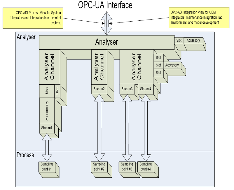
Figure 1 – High Level Object Model overview
For a detailed overview diagram of the ADI object model, refer to Figure 2. Elements illustrated in that diagram are further described in separate sections of this document..