In Figure 4 below an example is depicted to highlight the general modelling concepts that inform the design of the present OPC UA Companion Specification. The right hand side in white background shows the representation of the components of a cigarette maker machine, also simply Maker.
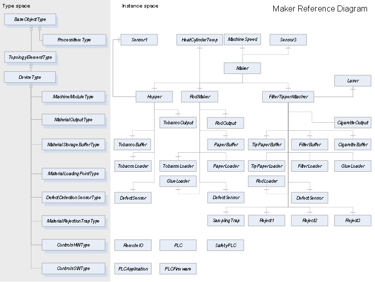
Figure 4 – Maker Reference Diagram
Special attention is paid to represent the flow of the product through the Maker components as depicted in Figure 5 by means of brown arrows. The model is required to identify all the components that interact with the product so that the flow procedes without interruption to the output of the machine. The product flow is modelled by means of a non-hierarchical reference named FlowsTo.
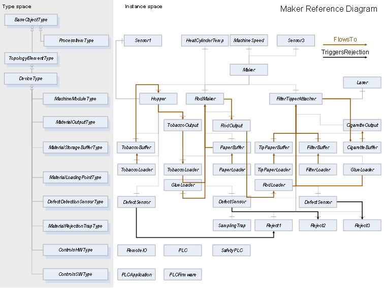
Figure 5 – Product Flow in the Maker Reference Diagram
The right-hand side of the diagram in white background is called Instance Space, i.e. the set of objects derived from the objects shown in the left-hand side of the diagram in grey background, the Type Space. The relationship between the instances and the types is conveniently shown in Figure 7.
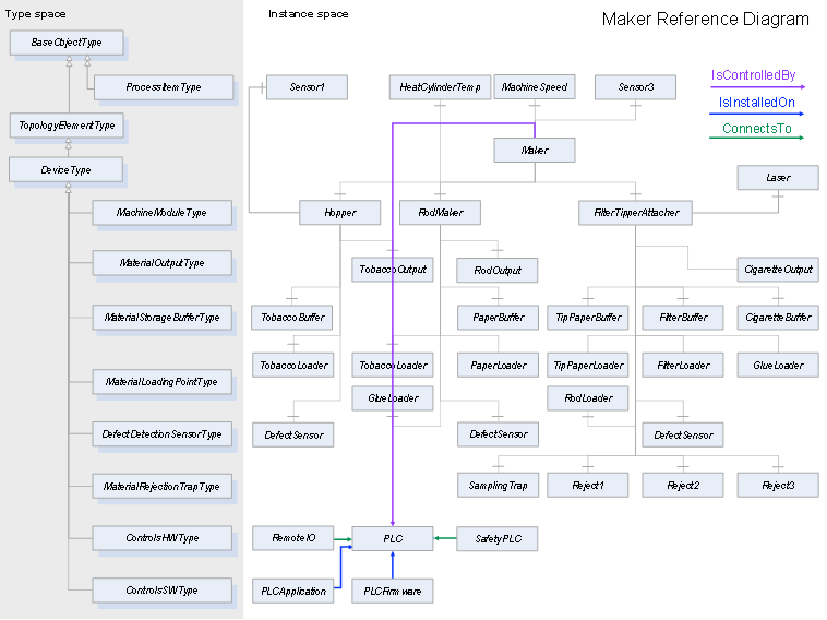
Figure 6 –Control architecture in the Maker Reference Diagram
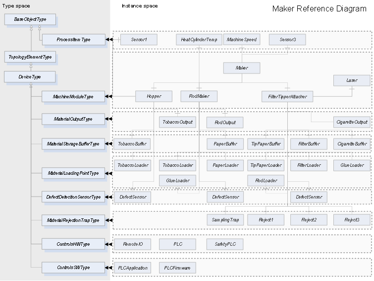
Figure 7 – Instances vs Types in the Maker Reference Diagram