CNC systems are used to control machine tools and machining centers. The CNC system is mainly responsible for generating a relative movement between a tool (e.g cutting tool) and a workpiece. Therefore, the CNC system implements functionality to provide setpoints to a machine tool’s drives that realize the generated movement physically.
CNC systems are in most cases executed in combination with Programmable Logic Controllers (PLC). Whereas the CNC is responsible for the tool path generation, the PLC implements auxiliary functionality (mostly logical operations like activating lubrication at a certain time) and controls the peripheral devices.
CNC systems as a whole consist of several hardware and software components as illustrated in Figure 1.
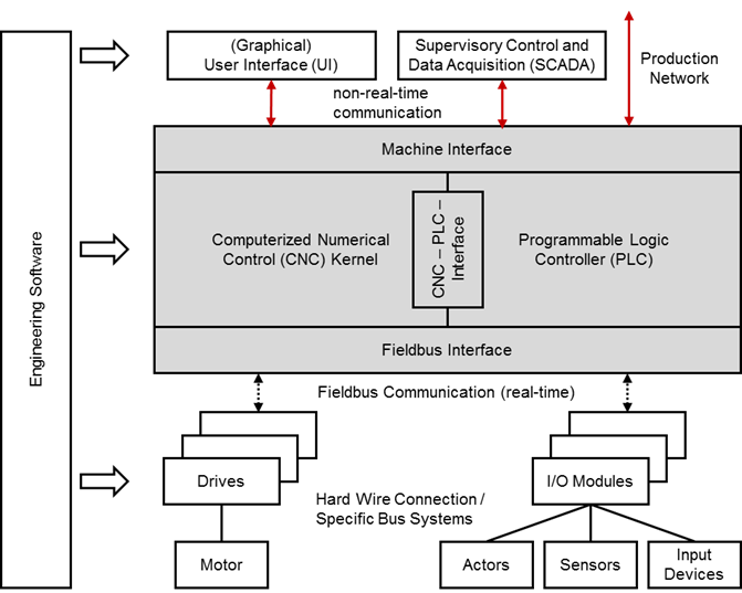
Figure 1 – Components of a CNC system
- Computerized Numerical Control Kernel (CNC kernel): The CNC kernel realizes the core functionality of a CNC system. It implements functionality to generate the axes movement for machining workpieces based on a geometrical and technological description given in a CNC part program. Therefore it provides software functions for decoding, interpreting and processing data of a CNC part program, for path planning and setpoint generation considering given constraints and depending on the system’s realization for positioning the machine’s axes.
- Programmable Logic Controller (PLC): The PLC handles all logical operations of a CNC system. It is closely coupled with the CNC kernel and enables to realize complex process sequences that involve different actors and sensors of the machine next to the machine’s drives. The PLC may also realize monitoring and safety functions and processes input signals from certain devices or the user interface. PLC programs are often implemented according to IEC 61131-3.
- CNC-PLC-Interface: The CNC-PLC-Interface links the CNC kernel and the PLC. Both modules have to be synchronized and therefore are closely coupled. The CNC-PLC-Interface is often realized as shared memory to allow high performing data exchange.
- Machine Interface: The Machine Interface allows applications to exchange data with a CNC system. Thus, the CNC system can be configured, operated and monitored. The Machine Interface is used primarily by the User Interface (UI) but additionally by other applications like engineering and production management systems. Many CNC systems offer more than one Machine Interface connection point so that different communication mechanisms or protocols can be used at a time.
- (Graphical) User Interface (UI): The UI, mostly realized as graphical user interface (GUI) is a software application that allows operators and commissioning engineers to interact with the CNC system and therefore to configure, operate and monitor the CNC system as well as the complete machine tool. The UI is connected to the Machine Interface of the CNC system. It may be executed on the same system platform than the CNC or on a separate device.
- Fieldbus Interface: The peripheral devices and the drives of a machine tool are connected to the CNC system by a fieldbus. For that reason both CNC and hardware device provide a Fieldbus Interface for connecting one with another. Most fieldbus systems allow to communicate data in a cyclical, time deterministic behaviour, as well as in an asynchronous mode.
- Drives and Motors: The drive unit, consisting of drive and motor, realizes physically the desired tool path, generated by the CNC kernel. The drive implements among others feedback controllers for current, velocity and mostly for position, as well. Generated setpoints are used for controlling the motor. The drive itself is connected to the CNC by a fieldbus to realize a time deterministic communication behaviour.
- I/O-Modules and Actors, Sensors, Input Devices: Apart from the drives, other peripheral devices (actors, sensors and input devices) are connected directly or through I/O-Modules to the CNC by a fieldbus.
Machine tools and machining centers can constitute complex systems regarding their kinematic structure. To cope with this complexity CNC systems provide the possibility to fragment the control task by using a software construct organizing kinematic chains and additional moving machine tool components like tool changers. So called “channels” are responsible for controlling smaller portions of the machine tool kinematic and its additional components. In general, all axes within a channel are interpolated in common.