Figure 10 shows an overview of the SafetyConsumer interfaces. The Safety Application Program Interface (SAPI) is specified in 6.3.4.2, the Safety Parameter Interface (SPI) is specified in 6.3.4.4.
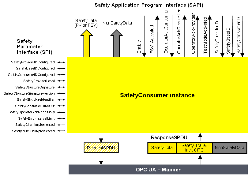
Figure 10 – SafetyConsumer interfaces
The SAPI of the SafetyConsumer represents the safety communication layer services of the SafetyConsumer. Table 25 lists all inputs and outputs of the SAPI of the SafetyConsumer.
[RQ6.14] Each SafetyConsumer shall implement the SAPI as shown in Table 25, however, the details are vendor-specific.
Table 25 – SAPI of the SafetyConsumer
|
SAPI Term |
Type |
I/O |
Definition |
|
SafetyData |
Structure |
O |
This output either delivers the process values received from the SafetyProvider in the SPDU field SafetyData, or FSV. |
|
NonSafetyData |
Structure |
O |
This output delivers the non-safety process values (e.g. diagnostic information) which were sent together with safe data, see 7.2.1.11 |
|
Enable |
Boolean |
I |
By changing this input to “0” the SafetyConsumer will change each and every Variable of the SafetyData to “0”1 and stop sending requests to the SafetyProvider. When changing Enable to “1” the SafetyConsumer will restart safe communication. The variable can be used to delay the start of the safety communication according to this document, after power on until “OPC UA connection ready” is set.The delay time is not monitored while enable is set to “0”. |
|
FSV_Activated |
Boolean |
O |
This output indicates via “1” that on the output SafetyData FSV (all binary “0”) are provided1. NOTE A ResponseSPDU which is checked with an error results in FSV_Activated being set to “1”, see T24 in Table 35. There could be other reasons. |
|
OperatorAckConsumer |
Boolean |
I |
For motivation, see 6.3.4.3. After an indication of OperatorAckRequested this input can be used to signal an operator acknowledgment. By changing this input from “0” to “1” (rising edge) the SafetyConsumer is instructed to switch SafetyData from FSV to PV. OperatorAckConsumer is processed only if this rising edge arrives after OperatorAckRequested was set to “1”, see Figure 19. If a rising edge of OperatorAckConsumer arrives before OperatorAckRequested becomes 1, this rising edge is ignored. |
|
OperatorAckRequested |
Boolean |
O |
This output indicates the request for operator acknowledgment. The bit is set to “1” by the SafetyConsumer, when three conditions are met: 1)Too many communication errors were detected in the past, so the SafetyConsumer decided to switch to fail-safe substitute values. 2)Currently, no communication errors occur, and hence operator acknowledgment is possible. 3)Operator acknowledgment (rising edge at input OperatorAckConsumer) has not yet occurred. The bit is reset to “0” when a rising edge at OperatorAckConsumer is detected. |
|
OperatorAckProvider |
Boolean |
O |
This output indicates that an operator acknowledgment has taken place on the SafetyProvider. If operator acknowledgment at the SafetyProvider should be allowed, this output is connected to OperatorAckConsumer, see B.3.4 and B.3.5. NOTE If the ResponseSPDU is checked with error, this output remains at its last value, see T24 in Table 35. |
|
TestModeActivated |
Boolean |
O |
The safety application program is expected to evaluate this output for determining whether the communication partner is in test mode or not. A value of “1” indicates that the communication partner (source of data) is in test mode, e.g. during commissioning. Data coming from a device in test mode may be used for testing but is not intended to be used to control safety-critical processes. A value of “0” represents the “normal” safety-related mode. The test mode enables the programmer and commissioner to validate the safety application using test data. NOTE If the ResponseSPDU check results in an error and the ErrorIntervalTimer (see 6.3.4.4) is also not expired, TestModeActivated is reset, see state S17_Error in Table 34. |
|
SafetyProviderID |
UInt32 |
I |
For dynamic systems, this input can be set to a non-zero value. In this case, the SafetyConsumer uses this variable instead of the SPI parameter SafetyProviderIDConfigured. This input is only read in the first cycle, or when a rising edge occurs at the input Enable. See also Table 26. If it is changed to “0”, the value of SPI parameter SafetyProviderIDConfigured will be used (again). For static systems, this input is usually always kept at value “0”. |
|
SafetyBaseID |
Guid |
I |
For dynamic systems, this input can be set to a non-zero value. In this case, the SafetyConsumer uses this variable instead of the SPI parameter SafetyBaseIDConfigured. This input is only read in the first cycle, or when a rising edge occurs at the input Enable. See also Table 26. If it is changed to “0”, the SPI parameter SafetyBaseIDConfigured will become activated. For static systems, this input is usually always kept at value “0”. |
|
SafetyConsumerID |
UInt32 |
I |
For dynamic systems, this input can be set to a non-zero value. In this case, the SafetyConsumer uses this variable instead of the SPI parameter SafetyConsumerID. This input is only read in the first cycle, or when a rising edge occurs at the input Enable. See also Table 26. If it is changed to “0”, the SPI parameter SafetyConsumerID will become activated. For static systems, this input is usually always kept at value “0”. |
|
1 If an application requires different FSV than “all binary 0”, it is expected to use appropriate constants and ignore the output of SafetyData whenever FSV_Activated is set. |
|||
The safety argumentation assumes that random errors in the underlying OPC UA stack including its communication links are not too frequent, i.e. that its failure rate is lower than a given threshold, depending on the desired SIL (see 9.3.1).
Whenever the SafetyConsumer detects a faulty message, it checks whether the assumption is still valid, and switches to fail-safe substitute values otherwise. Returning to process values then requires an operator acknowledgment.
Operator Acknowledge is expected to be initiated by a human operator who is responsible to check the installation, see Table 40, row “Operator Acknowledge”. For this reason, the parameter OperatorAckRequested is delivered by the SafetyConsumer to the safety application. See Clause B.2 for details on operator acknowledgment scenarios.
Timeout errors do only require an operator acknowledgment if operator acknowledgment is required by the safety function itself. In this case, SafetyOperatorAckNecessary is set to indicate that operator acknowledgments are required. See 6.3.4.5 for details.
[RQ6.15a] Each SafetyConsumer shall implement the parameters and constants [RQ6.15b] as shown in Table 26. The parameters (R/W in column “Access”) can be set via the SPI, whereas the constants (R in column “Access”) are read-only. The mechanisms for setting these parameters are vendor-specific. The attempt of setting a parameter to a value outside its range, or of the setting of a read-only parameter, shall not become effective, and a diagnostic message should be shown when appropriate. The SPI of the SafetyConsumer represents the parameters of the safety communication layer management of the SafetyConsumer. The values of the constants depend on the way the SafetyConsumer is implemented. They never change and are therefore not writable via any of the interfaces.
Table 26 – SPI of the SafetyConsumer
|
Identifier |
Type |
Valid range |
Initial value (before configuration) |
Access |
Note |
|
SafetyProviderIDConfigured |
UInt32 |
0x0 to 0xFFFFFFFF |
0x0 |
R/W |
The default SafetyProviderID of the SafetyProvider this SafetyConsumer uses to make a connection, see Figure 8 and 3.1.2.15. For dynamic systems, the safety application program can overwrite this ID by providing a non-zero value at the input SafetyProviderID of the SafetyConsumer’s SAPI. This runtime value can be queried using the SafetyProviderIDActive parameter. See 6.2.2.6 for details on configured and active values. |
|
SafetyBaseIDConfigured |
Guid |
Any value which can be represented with sixteen octets. |
All sixteen octets are 0x0 |
R/W |
The default SafetyBaseID of the SafetyProvider this SafetyConsumer uses to make a connection, see 3.1.2.14. For dynamic systems, the safety application program can overwrite this ID by providing a non-zero value at the input SafetyBaseID of the SafetyConsumer’s SAPI. This runtime value can be queried using the SafetyBaseIDActive parameter. See 6.2.2.6 for details on configured and active values. |
|
SafetyConsumerIDConfigured |
UInt32 |
0x0 to 0xFFFFFFFF |
0x0 |
R/W |
SafetyConsumerID of the SafetyConsumer, see 9.1.2. For dynamic systems, the safety application program can overwrite this ID by providing a non-zero value at the input SafetyConsumerID of the SafetyConsumer’s SAPI. This runtime value can be queried using the SafetyConsumerIDActive parameter. See 6.2.2.6 for details on configured and active values. |
|
SafetyProviderLevel |
Byte |
0x01 to 0x04 |
0x04 |
R/W |
SafetyConsumer’s expectation on the SIL the SafetyProvider implementation (hardware and software) is capable of. See 3.1, 7.2.3.4, and Figure 9. |
|
SafetyStructureSignature |
UInt32 |
0x0 to 0xFFFFFFFF |
0x0 |
R/W |
Signature over the SafetyData structure, see 7.2.3.5. |
|
SafetyStructureSignatureVersion |
UInt16 |
0x1 |
0x1 |
R/W |
Version used to calculate SafetyStructureSignature, see 7.2.3.5. For the SafetyConsumer, this parameter is optional. |
|
SafetyStructureIdentifier |
String |
|
“” |
R/W |
Identifier describing the DataType of the SafetyData, see 7.2.3.5. For the SafetyConsumer, this parameter is optional. |
|
SafetyConsumerTimeout |
UInt32 |
0x0 to 0xFFFFFFFF |
0x0 |
R/W |
Watchdog-time in microseconds (µs). Whenever the SafetyConsumer sends a request to a SafetyProvider, its watchdog timer is set to this value. The expiration of this timer prior to receiving an error-free reply by the SafetyProvider indicates an unacceptable delay. See 8.1 |
|
SafetyOperatorAckNecessary |
Boolean |
0x0 or 0x1 |
0x1 |
R/W |
This parameter controls whether an operator acknowledgment (OA) is necessary in case of errors of type “unacceptable delay” or “loss”, or when the SafetyProvider has activated FSV (ActivateFSV). 1: FSV are provided at the output SafetyData of the SAPI until OA. 0: PV are provided at SafetyData of the SAPI as soon as the communication is free of errors. In case of ActivateFSV the values change from FSV to PV as soon as ActivateFSV returns to “0”. NOTE This parameter does not have an influence on the behaviour of the SafetyConsumer following the detection of other types of communication errors, such as data corruption or an error detected by the SPDU_ID. For these types of errors, OA is mandatory, see 6.3.4.3. |
|
SafetyErrorIntervalLimit |
UInt16 |
6, 60, 600 |
600 |
R/W |
Value in minutes. The parameter SafetyErrorIntervalLimit determines the minimal time interval between two consecutive communication errors so that they do not trigger a switch to FSV in the SafetyConsumer, see 6.3.4.3. It affects the availability and either the PFH or PFDavg, or both, of the safety communication link according to this document, see 9.4. |
|
SafetyClientImplemented |
Boolean |
0x0 or 0x1 |
n.a. |
R |
This read-only parameter indicates whether the SafetyConsumer has implemented the client part of OPC UA Client/Server communication (see 5.4): 1: Client for OPC UA Client/Server communication is implemented. 0: Client for OPC UA Client/Server communication is not implemented. The corresponding Facet is SafetyConsumerClient. |
|
SafetyPubSubImplemented |
Boolean |
0x0 or 0x1 |
n.a. |
R |
This read-only parameter indicates whether the SafetyConsumer has implemented the necessary publishers and subscribers for OPC UA PubSub communication (see 5.4): 1: OPC UA PubSub communication is implemented. 0: OPC UA PubSub communication is not implemented. The corresponding Facets are SafetyConsumerPubSub and SafetyConsumerPubSubMapper. |
This parameter determines whether automatic restart (i.e. automatically switching back from fail-safe values to process values) is possible for the safety function or not. It is expected to be set to 1 for safety functions where automatic restart is not allowed and restart always requires human interaction.
If automatic restart of the safety function is safe, the parameter can be set to 0.