[RQ6.13a] Each SafetyProvider shall implement the parameters and constants [RQ6.13b] as shown in Table 24. The parameters (R/W in column “Access”) can be set via the SPI, whereas the constants (R in column “Access”) are read-only. The mechanisms for setting the parameters are vendor-specific. The attempt of setting a parameter to a value outside its range, or of the setting of a read-only parameter, shall not become effective, and a diagnostic message should be shown when appropriate. The values of the constants depend on the way the SafetyProvider is implemented. They never change and are therefore not writable via any of the interfaces.
Table 24 – SPI of the SafetyProvider
|
Identifier |
Type |
Range |
Initial value (before configuration) |
Access |
Note |
|
SafetyProviderIDConfigured |
UInt32 |
0x0 to 0xFFFFFFFF |
0x0 |
R/W |
SafetyProviderID of the SafetyProvider that is normally used, see 3.1.2.15 and 9.1.1. For dynamic systems, the safety application program can overwrite this ID by providing a non-zero value at the input SafetyProviderID of the SafetyProvider’s SAPI. This runtime value can be queried using the SafetyProviderIDActive parameter. See 6.2.2.6 for details on configured and active values. NOTE If both the values provided at the SPI and the SAPI are 0x0, this means that the SafetyProvider is not properly configured. SafetyConsumers will never try to communicate with SafetyProviders having a SafetyProviderID of 0x0, see Transitions T13/T27 in Table 35 and the macro <ParametersOK?> in Table 33. |
|
SafetyBaseIDConfigured |
Guid |
Any value which can be represented with sixteen octets |
All sixteenoctets are 0x00 |
R/W |
SafetyBaseID of the SafetyProvider that is normally used, see 3.1.2.14 and 9.1.1. For dynamic systems, the safety application program can overwrite this ID by providing a non-zero value at the input SafetyBaseID of the SafetyProvider’s SAPI. This runtime value can be queried using the SafetyBaseIDActive parameter. See 6.2.2.6 for details on configured and active values. NOTE If both the values provided at the SPI and the SAPI are 0x0, this means that the SafetyProvider is not properly configured. SafetyConsumers will never try to communicate with SafetyProviders having a SafetyBaseID of 0x0, see Transitions T13/T27 in Table 35 and the macro <ParametersOK?> in Table 33. |
|
SafetyProviderLevel |
Byte |
0x01 to 0x04 |
n.a. |
R |
The SIL the SafetyProvider implementation (hardware and software) is capable of, see Figure 9. NOTE 1 It is independent from the generation of the SafetyData at SAPI. NOTE 2 The SafetyProviderLevel is used to distinguish devices of a different SIL. As a result, SPDUs coming from a device with a low SIL will never be accepted when a SafetyConsumer is parameterized to implement a safety function with a high SIL. |
|
SafetyStructureSignature |
UInt32 |
0x0 to 0xFFFFFFFF |
0x0 |
R/W |
Signature of the SafetyData structure, for calculation see 7.2.3.5. NOTE “0” would not be a valid signature and thus indicates a SafetyProvider which is not properly configured. SafetyConsumers will never try to communicate with SafetyProviders having a SafetyStructureSignature of 0x0, see Transitions T13/T27 in Table 35 and the macro <ParametersOK?> in Table 33. |
|
SafetyStructureSignatureVersion |
UInt16 |
0x1 |
0x1 |
R/W |
Version used to calculate SafetyStructureSignature, see 7.2.3.5 |
|
SafetyStructureIdentifier |
String |
all strings |
“” (the empty string) |
R/W |
Identifier describing the DataType of the SafetyData, see 7.2.3.5. |
|
SafetyProviderDelay |
UInt32 |
0x0 to 0xFFFFFFFF |
0x0 |
R/W |
In microseconds (µs). It can be set during the engineering phase of the SafetyProvider or set during online configuration as well. SafetyProviderDelay is the maximum time at the SafetyProvider from receiving the RequestSPDU to start the transmission of ResponseSPDU, see 8.1. The parameter SafetyProviderDelay has no influence on the functional behaviour of the SafetyProvider. Therefore, it is not necessary for this value to be generated in a safety-related way. However, it will be provided in the OPC UA Information Model of a SafetyProvider to inform about its worst-case delay time. The value can be used during commissioning to check whether the timing behaviour of the SafetyProvider is suitable to fulfill the watchdog delay of the corresponding SafetyConsumer. |
|
SafetyServerImplemented |
Boolean |
0x0 or 0x1 |
n.a. |
R |
This read-only parameter indicates whether the SafetyProvider has implemented the Server part of OPC UA Client/Server communication (see 5.4): 1: Server for OPC UA Client/Server communication is implemented. 0: Server for OPC UA Client/Server communication is not implemented. The corresponding Facets are SafetyProviderServer and SafetyProviderServerMapper. |
|
SafetyPubSubImplemented |
Boolean |
0x0 or 0x1 |
n.a. |
R |
This read-only parameter indicates whether the SafetyProvider has implemented the necessary publishers and subscribers for OPC UA PubSub communication (see 5.4): 1: OPC UA PubSub communication is implemented. 0: OPC UA PubSub communication is not implemented. The corresponding Facets are SafetyProviderPubSub and SafetyProviderPubSubMapper. |
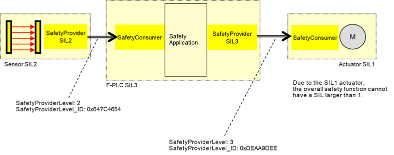
Figure 9 – Example combinations of SIL capabilities
The constant SafetyProviderLevel determines the value that is used for SafetyProviderLevel_ID when calculating the SPDU_ID, see 7.2.3.4.
NOTE SafetyProviderLevel is defined as the SIL the SafetyProvider implementation (hardware and software) is capable of, not to be confused with the SIL of the implemented safety function. For instance, Figure 9 shows a safety function which is implemented using a SIL 2-capable sensor, a SIL 3-capable PLC, and a SIL 1-capable actuator. The overall SIL of the safety function is considered to be SIL 1. Nevertheless, the SafetyProvider implemented on the sensor will use the constant value “2” as SafetyProviderLevel, whereas the SafetyProvider implemented on the PLC will use the constant value “3” as SafetyProviderLevel.
It is necessary for the respective SafetyConsumers (on the PLC and the actuator) to know the SafetyProviderLevel of their SafetyProviders in order to check the SPDU_ID (see 7.2.3.2).