The MonitoredParameterType is used for process parameters that are monitored by the client.
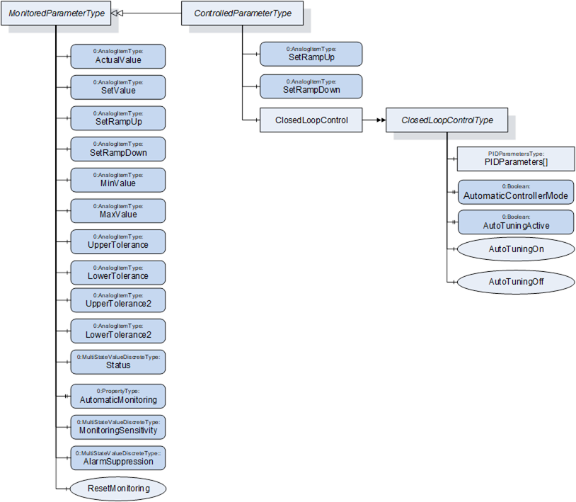
Figure 17 – MonitoredParameterType Overview
Table 126 – MonitoredParameterType Definition
|
Attribute |
Value |
||||
|
BrowseName |
MonitoredParameterType |
||||
|
IsAbstract |
False |
||||
|
References |
Node Class |
BrowseName |
DataType |
TypeDefinition |
Other |
|
Subtype of 0:BaseObjectType defined in OPC UA Part 5 |
|||||
|
0:HasComponent |
Variable |
ActualValue |
0:Double |
0:AnalogItemType |
M, RO |
|
0:HasComponent |
Variable |
SetValue |
0:Double |
0:AnalogItemType |
O, RW |
|
0:HasComponent |
Variable |
SetRampUp |
0:Double |
0:AnalogItemType |
O, RO |
|
0:HasComponent |
Variable |
SetRampDown |
0:Double |
0:AnalogItemType |
O, RO |
|
0:HasComponent |
Variable |
MinValue |
0:Double |
0:AnalogItemType |
O, RW |
|
0:HasComponent |
Variable |
MaxValue |
0:Double |
0:AnalogItemType |
O, RW |
|
0:HasComponent |
Variable |
UpperTolerance |
0:Double |
0:AnalogItemType |
O, RW |
|
0:HasComponent |
Variable |
LowerTolerance |
0:Double |
0:AnalogItemType |
O, RW |
|
0:HasComponent |
Variable |
UpperTolerance2 |
0:Double |
0:AnalogItemType |
O, RW |
|
0:HasComponent |
Variable |
LowerTolerance2 |
0:Double |
0:AnalogItemType |
O, RW |
|
0:HasComponent |
Variable |
Status |
0:UInt16 |
0:MultiStateValueDiscreteType |
O, RO |
|
0:HasProperty |
Variable |
AutomaticMonitoring |
0:Boolean |
0:PropertyType |
O, RW |
|
0:HasComponent |
Variable |
MonitoringSensitivity |
0:UInt16 |
0:MultiStateValueDiscreteType |
O, RW |
|
0:HasComponent |
Variable |
AlarmSuppression |
0:UInt16 |
0:MultiStateValueDiscreteType |
O, RW |
|
0:HasComponent |
Method |
ResetMonitoring |
|
|
O |
|
0:HasSubtype |
ObjectType |
ControlledParameterType |
Defined in Clause 23 |
||
Actual value of the monitored parameter (unit given in AnalogItemType).
Set/nominal/target value of the monitored parameter. The value of this variable is writeable by the client. As the MonitoredParameterType is not used to control parameters, this is only for information/Process monitoring and not for changing setting on the device.
NOTE: For controlling parameters the ControlledParameterType is defined in Clause 23.
Indication if a SetValue that is higher than the actual value shall be reached as fast as possible (SetRampUp = 0) or within a given value change per time (e.g. SetRampUp = 2 K/s).
Indication if SetValue that is lower than the actual value shall be reached as fast as possible (SetRampDown = 0) or within a given value change per time (e.g. SetRampDown = 2 K/s).
NOTE: Always positive value.
These parameters are used to define limits for the monitored parameter. Exceeding the (relative) tolerance values creates a warning while exceeding the (absolute) Min/MaxValues leads to an alarm from type MonitoredParameterAlarmType and/or perhaps other actions on the machine (e.g. switching off the heating, stopping of movements) as defined by the severity level. With UpperTolerance2 and LowerTolerance2 a second tolerance band can be defined.
NOTE: When UpperTolerance and/or LowerTolerance are used, the SetValue shall be also given.
NOTE: When UpperTolerance2 and/or LowerTolerance2 are used, UpperTolerance and/or LowerTolerance shall be also given. UpperTolerance2 shall be between UpperTolerance and MaxValue. LowerTolerance2 shall be between LowerTolerance and MinValue.
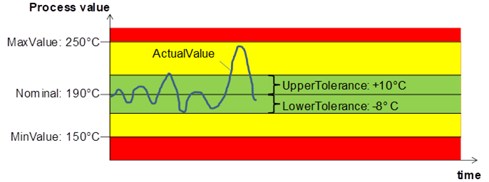
Figure 18 – Values in MonitoredParameterType (here only one tolerance band is shown)
Information if the ActualValue is within the tolerances or has passed a tolerance or min/max value. The TypeDefinition is MultiStateValueDiscreteType, so the Properties EnumValues and ValueAsText shall be filled with the supported values out of Table 127.
|
EnumValue |
ValueAsText |
Description |
|
0 |
NONE |
No monitoring |
|
1 |
UNKNOWN |
Status not known, e.g. because of broken sensor |
|
2 |
BELOW_MIN_VALUE |
ActualValue is below MinValue |
|
3 |
BELOW_LOWER_TOLERANCE2 |
ActualValue is below LowerTolerance2 |
|
4 |
BELOW_LOWER_TOLERANCE |
ActualValue is below LowerTolerance |
|
5 |
WITHIN_TOLERANCE |
ActualValue is between LowerTolerance and UpperTolerance |
|
6 |
ABOVE_UPPER_TOLERANCE |
ActualValue is above UpperTolerance |
|
7 |
ABOVE_UPPER_TOLERANCE2 |
ActualValue is above UpperTolerance2 |
|
8 |
ABOVE_MAX_VALUE |
ActualValue is above MinValue |
Determination if monitoring tolerance parameters are determined by auto-tuning itself (TRUE) or can be manually adjusted (FALSE). If TRUE the monitoring tolerance parameters are determined by auto-tuning regarding the set monitoring sensitivity (if used). In this case, the tolerance parameters shall then be not writeable.
The monitoring sensitivity defines how closely the tolerances are set during the automatic limit setting. The TypeDefinition is MultiStateValueDiscreteType, so the Properties EnumValues and ValueAsText must be filled with the supported values out of Table 128.
Table 128 – Values for MonitoringSensitivity
|
EnumValue |
ValueAsText |
Description |
|
0 |
FINE |
tight tolerances |
|
1 |
MIDDLE |
mean tolerances |
|
2 |
ROUGH |
large tolerances |
The absolute widths of the set tolerance bands are device dependent.
The alarm suppression deactivates alarms of a monitored parameter e.g. during start up or a setpoint jump. The TypeDefinition is MultiStateValueDiscreteType, so the Properties EnumValues and ValueAsText must be filled with the supported values out of Table 129.
Table 129 – Values for AlarmSuppression
|
EnumValue |
ValueAsText |
Description |
|
0 |
OFF |
no alarm suppression |
|
1 |
HORN |
suppressed only horn |
|
2 |
COMPLETE |
alarm contact, alarm via interface and horn suppressed |
Description:With this method the tolerance values are set according to the actual value and the set monitoring sensitivity. This can be used e.g. after a process change with new SetValue to adapt the monitoring.
Signature
ResetMonitoring ();
The method has no Input- or OutputArguments.
Table 130 – ResetMonitoring Method AddressSpace Definition
|
Attribute |
Value |
||||
|
BrowseName |
ResetMonitoring |
||||
|
References |
Node Class |
BrowseName |
DataType |
TypeDefinition |
Modelling Rule |