Figure 11 shows the general model and the central object types of this companion specification.
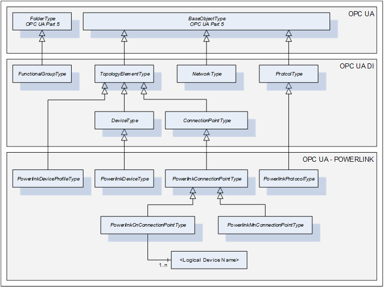
Figure 11 – POWERLINK OPC UA model overview
POWERLINK Objects are represented by OPC UA Variables as part of the PowerlinkConnectionPointType and its subtypes. A PowerlinkConnectionPointType contains common Variables while the subtypes contain only the Variables that are specific to the POWERLINK Controlled Node and the POWERLINK Managing Node.
Instances of subtypes of PowerlinkConnectionPointType are used to represent the POWERLINK Object Dictionary of a POWERLINK Device. The subtypes of ConnectionPointType are used to extend a Device (not limited to PowerlinkDeviceType) by one or more POWERLINK Object Dictionaries.
The PowerlinkDeviceType is used to represent a typical POWERLINK Device and defines a standardised way to generate the mandatory Properties for a DeviceType (like SerialNumber, RevisionCounter, etc.) from values of certain POWERLINK Objects. In case a Device implements more than one POWERLINK interface (by implementing multiple ConnectionPoints), the selection of the ConnectionPoint as source for the DeviceType Properties is implementation specific.
Figure 12 shows an example for a Device (DeviceExample1) that implements an instance of a POWERLINK Controlled Node and another Device (DeviceExample2) that implements two instances of a POWERLINK Managing Node.
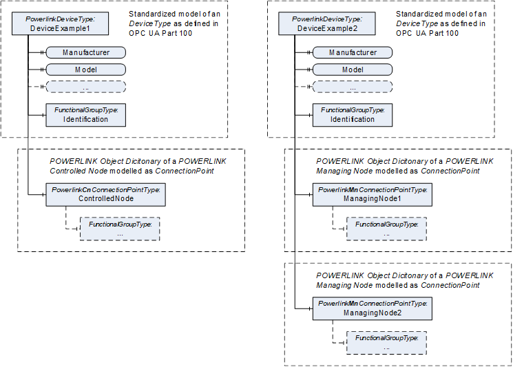
Figure 12 – PowerlinkDeviceType example for POWERLINK Controlled Node
The focus of this document is the detailed specification of the POWERLINK Objects of the communication profile EPSG DS 301 and EPSG DS 302, but it also defines the modelling rules for the implementation of specific POWERLINK Device Profiles.
Figure 13 shows how to add device profile specific POWERLINK Objects to the existing definition for the communication profile. The modelling rules are defined in 5.2.
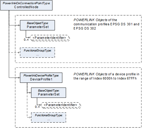
Figure 13 – Model of a POWERLINK Device Profile