Using the same modeling approach as described above you can easily add an additional information layer giving detailed information on the connectors and pinout of the cables in the system. If needed, you may even provide a full cabling plan for the whole system.
The models are simple but will become very large (you often hear people saying otherwise, but no, size and complexity are not the same thing).
Please keep in mind that such models are not intended to be made or read by human beings. A cabling plan will be an output of your engineering software and should be read by a service tool helping a service technician doing maintenance or error analysis.
The first thing to do is to add some connectors to the cable model.
Below is an example of a Y-cable with one connector on one end that is split to 2 connectors on the other end.
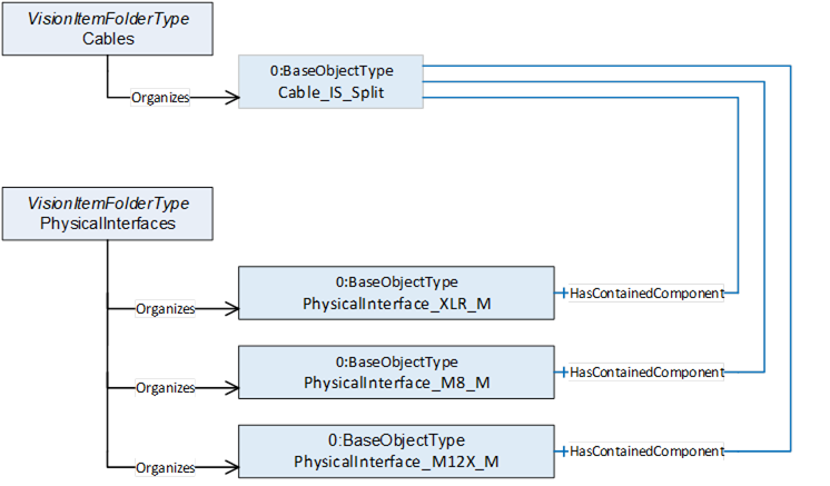
Figure 65 – Detailed modelling of cables
To show the pinout of the connectors we add the wires of the cable to the Cables folder and the pins of the connectors to the PhysicalInterfaces folder. We use the IsPhysicallyConnectedTo reference type to show how everything is wired.
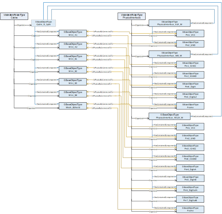
Figure 66 – Detailed modelling of cables
If the cable gets connected to a device, you may decide at which level of information depth you reflect this. The connector of the cable gets physically connected to the fitting connector of the device. You may also show that each pin gets connected which may make it easier to browse large cable trees later on.
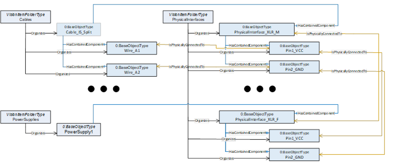
Figure 67 – Detailed modelling of cables
Note: In industrial applications it is common to use screw terminals instead of connectors to connect cables. But even in this case you often need to give detail information on how this end of the cable has to be manufactured. Do you simply have to strip the isolation, or do you need to put on a cable shoe and if yes what type and size of shoe is needed?
An “Open End” object (analog to a pin object) would be a good place to store such information.