As we saw above, our models show relations between devices / components. We may add further layers of information to give more details, e.g., to show that a control flow between devices is dependent on cables connecting them.
In a machine vision system, we do not only care about electrical signals being distributed.
We also care about the distribution of light to be able to answer questions like:
Why do I get no image?
Why is the image I get not as bright as expected?
To be able to model optical relations we introduced an additional reference type called OpticalPath for that purpose.
Note: As our Industry is called machine vision, we use to speak of images coming from a sensor. This could be something like a photo, but often it is something different which would not be called an image in everyday circumstances.
In the same way we use the terms light and optics in a very general way. “Light” can be anything you use to get your “image”, it could be Infrared light, could be X-ray or could even be a sound wave. Everything used to guide or manipulate your “source signal” we call “optical equipment” and the source of that signal we call “lamp”.
We also introduced an SurroundingEnvironment Object. In real world applications you often struggle with the surrounding environment around your Vision System. Maybe you make use of ambient light to make your images or maybe scattered ambient light ruins your image processing if you can’t isolate the system well enough.
In both cases, it is very often necessary to monitor “surrounding environment quality”, meaning the influence the surroundings have on your application (e.g., brightness of ambient light, ambient temperature).
The surrounding environment object is the right place to store such information.
A similar object is the AcquisitionBackground. If for example you need to be able to correctly “see” the contour of an object of interest, you will have some requirements on what is behind that object. So often the background is monitored to warn about dirt and debris showing up before it influences the quality of your image processing. As the acquisition background is often a part of the system (e.g., a gray sheet of metal or a backlight) we distinguished it from the surrounding environment, that is what we find around the vision system.
But back to the optical path.
In the example vision system shown at the beginning of this chapter we can identify 3 main optical paths via which light can reach the image sensor.
- Lamp1 in conjunction with a semitransparent mirror is used to illuminate the surface of our object of interest.
- A backlight Lamp2 is used to be able to see the contour of the object. Some of that light is lost as it has to pass the mirror used for front face illumination
- Stray light from the surrounding environment may disturb our image, as it is not completely blocked in that application
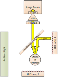
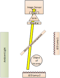
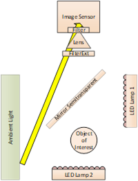
Figure 69 – Optical Paths in the example
This gives us the following model
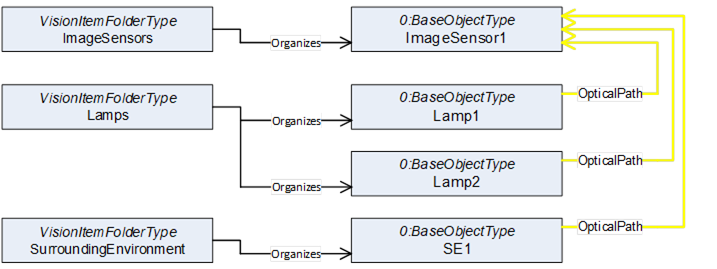
Figure 70 – Modelling of Optical Paths
Using the same approach as we did with the cables we now can include all intermediate objects that are part of these paths of light. As shown above to express a “Path” we need to use reference refinements to give the single references an order to build a path.
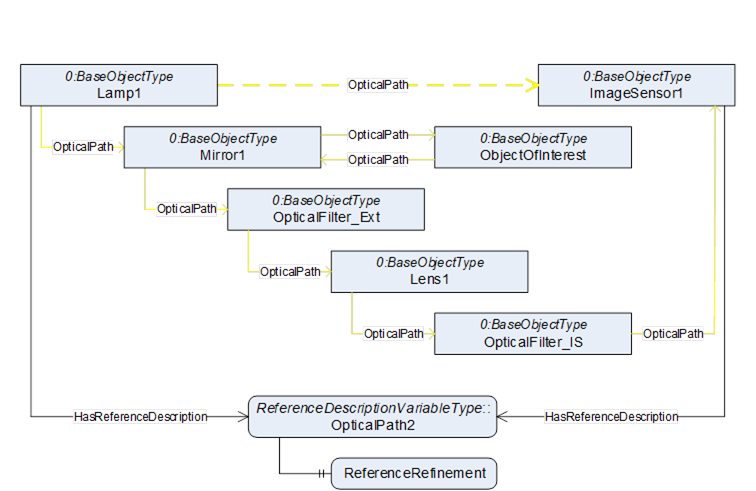
Figure 71 – Optical Path 1: Lamp 1 to Image Sensor
ReferenceDescription Value of OpticalPath1
SourceNode:Lamp1
ReferenceType:OpticalPath
IsForward:TRUE
TargetNode:ImageSensor1
ReferenceRefinement of OpticalPath3
{
ReferenceListEntry
ReferenceType:OpticalPath
IsForward:TRUE
TargetNode:Mirror1;
ReferenceListEntry
ReferenceType:OpticalPath
IsForward:TRUE
TargetNode:ObjectOfInterest;
ReferenceListEntry
ReferenceType:OpticalPath
IsForward:TRUE
TargetNode:Mirror1;
ReferenceListEntry
ReferenceType:OpticalPath
IsForward:TRUE
TargetNode:OpticalFilter_Ext;
ReferenceListEntry
ReferenceType:OpticalPath
IsForward:TRUE
TargetNode:Lens1;
ReferenceListEntry
ReferenceType:OpticalPath
IsForward:TRUE
TargetNode:OpticalFilter_IS;
ReferenceListEntry
ReferenceType:OpticalPath
IsForward:TRUE
TargetNode:ImageSensor1;
};
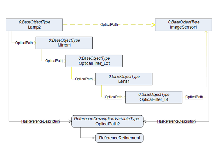
Figure 72 – Optical Path 2: Lamp 2 to Image Sensor
ReferenceDescription Value of OpticalPath2
SourceNode:Lamp2
ReferenceType:OpticalPath
IsForward:TRUE
TargetNode:ImageSensor1
ReferenceRefinement of OpticalPath2
{
ReferenceListEntry
ReferenceType:OpticalPath
IsForward:TRUE
TargetNode:Mirror1;
ReferenceListEntry
ReferenceType:OpticalPath
IsForward:TRUE
TargetNode:OpticalFilter_Ext;
ReferenceListEntry
ReferenceType:OpticalPath
IsForward:TRUE
TargetNode:Lens1;
ReferenceListEntry
ReferenceType:OpticalPath
IsForward:TRUE
TargetNode:OpticalFilter_IS;
ReferenceListEntry
ReferenceType:OpticalPath
IsForward:TRUE
TargetNode:ImageSensor1;
};
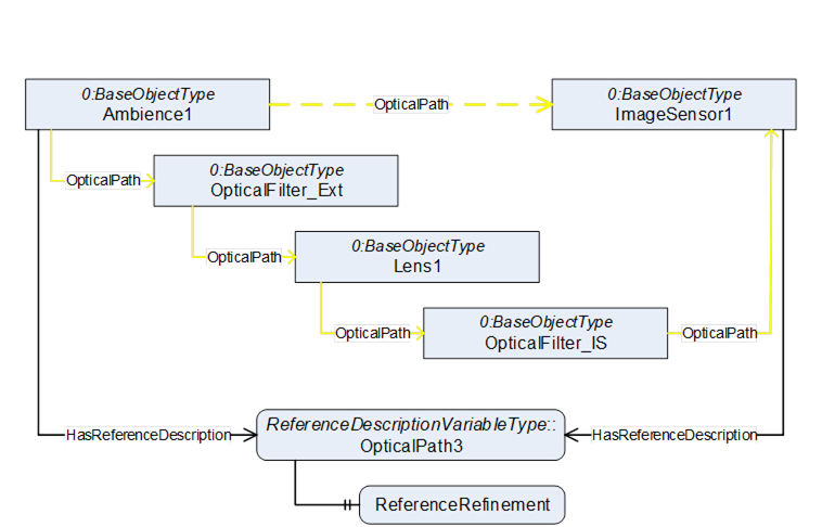
Figure 73 – Optical Path 3: Ambience to Image Sensor
ReferenceDescription Value of OpticalPath3
SourceNode:Ambience1
ReferenceType:OpticalPath
IsForward:TRUE
TargetNode:ImageSensor1
ReferenceRefinement of OpticalPath3
{
ReferenceListEntry
ReferenceType:OpticalPath
IsForward:TRUE
TargetNode:OpticalFilter_Ext;
ReferenceListEntry
ReferenceType:OpticalPath
IsForward:TRUE
TargetNode:Lens1;
ReferenceListEntry
ReferenceType:OpticalPath
IsForward:TRUE
TargetNode:OpticalFilter_IS;
ReferenceListEntry
ReferenceType:OpticalPath
IsForward:TRUE
TargetNode:ImageSensor1;
};
Browsing this model may aid you to answer the questions above. If you do not get the normal amount of brightness in the image you are taking from the front face of the object of interest, you may need to check if the mirror or the filter needs cleaning, as the light for that image must pass both.