This overview of the DEXPI information model is part of the journal paper titled “ENPRO Data Integration: Extending DEXPI Towards the Asset Lifecycle” (https://onlinelibrary.wiley.com/doi/full/10.1002/cite.201800112) (see section 2 - Normative references); please refer to that article for more details.
An important outcome of the DEXPI P&ID project is the specification document (see section 2 - Normative references). It contains the data models for the plant break down structure, for the taxonomies and properties of the apparatuses & machines, of the piping components and of the instrumentation objects. The topology between the different engineering objects is included as well. All engineering objects and properties are defined with the ISO 15926 sandbox concept, i.e. the POSC Caesar sandbox is the preferred industry sandbox, and the DEXPI sandbox contains additional ISO 15926 part 4 class definitions. The DEXPI data model uses multiple inheritance, a paradigm not compatible with OPC UA (an ObjectType can inherit from only one parent). An additional table with hierarchical relations between the DEXPI classes is part of the DEXPI data model and provides the information needed for the parent-child relationships in the DEXPI OPC UA address space model. As basis of implementation the Proteus schema [6] was selected by the software vendors and has been upgraded to the version 4.0.1 to fulfill the DEXPI requirements. Among other aspects the Proteus schema contains the graphical concept. Proteus is one implementation method for the DEXPI P&ID specification. Alternative technologies could be part 3 of ISO 15926 or the SVG (Scalable Vector Graphics) format. Two additional data sources for the DEXPI information model are the herarch of the DEXPI class taxonomy and the mapping of engineering units (see Normative references section). The data modeling approaches for the various parts of a P&ID will be introduced in the next subsections.
The plant break down structure and the identification concepts for engineering objects are important parts of an intelligent P&ID. The ISO 10209:2012 [7] contains essential specifications for these topics. DEXPI decided to use the following hierarchical structure described in Figure 8. Every plant item like a pump, a vessel or a pipe line is a tagged object and can be identified by a tag name, which is unique in the scope of a process plant. A process plant has a unique name in the scope of an enterprise’s site. Components of tagged objects like nozzles of a vessel have a sub tag identification concept, they always have a unique name in the scope of its tag. The DEXPI specification also supports some other structural elements like area, train or system. Every plant item can have references to those elements.
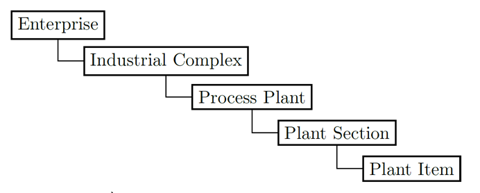
Figure 8 - Hierarchical structure used by the DEXPI group
For apparatuses and machines there are different taxonomies. The ISO Standard Maintenance Portal contains a classification into the groups Heat Transfer, Rotating Equipment, Solid Handling and Static equipment. The PAS 1041 contains a list of the apparatus and machines with 22 groups and a total of 198 single elements, with an entry in the 4-stage eclass hierarchy in each case. BASF, Bayer, Covestro and Evonik apply enterprise-specific taxonomies which they have implemented in their technical systems. Another possibility for the classification arises from the ISO 10628-2:2012. Out of 29 defined groups 24 concern apparatuses and machines. Within these groups symbols are assigned to different subtypes. Many CAE systems for P&IDs use these symbols from ISO 10628. The DEXPI concept is a synthesis from all these input dimensions, however the groups of ISO 10628 deliver the leading classification concept. Figure 9 illustrates the DEXPI apparatuses and machines data model applied to a pump example.
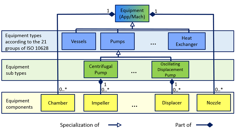
Figure 9 - DEXPI apparatuses and machines data model applied to a pump example
Sub equipment types always are specializations of equipment types. DEXPI
supports the component concept as a decomposition approach. Some components belong to specific sub-equipment types while other are more general and belong to the top-level equipment type. E.g.
every equipment can have Nozzles or Chambers, components that are more specific, like an Impeller, are part of a CentrifugalPump. All these engineering objects and their properties have been specified as ISO 15926 part 4 classes in the used sandboxes.
For the P&ID piping taxonomy, ISO 10628-2:2012 is the major source as well. Valves and fittings with safety functions are part of the piping discipline, not of instrumentation. A pipeline as a PipingNetworkSystem and a single segment as a PipingNetworkSegment are terms of the ISO 15926 specification. Uniform rules were fixed in collaboration with the CAE vendors for breaks by Piping Network Segments. Essential properties of the pipings, their segments and their components are media, pipe classes, nominal diameter, isolation and heating requirement information. A pipeline number is unique within a process plant; piping segments get a segment number which is combined with the corresponding pipeline number to get a unique identifier. All piping components as well get a plant-wide unique number as an identification. The development of the working package “Instrumentation” was by far the biggest and most time consuming challenge in the DEXPI project because the representation of the instrumentation in the P&ID is used very differently in various standards and enterprises. Moreover, the ISO Community has not yet delivered a comprehensive solution. Additionally, Proteus XML contained no adequate concept in the version 3.3.0 which was current at the time the DEXPI project started. On the engineering side, especially the instrumentation standards ISA 5.1 and IEC 62424 as well as the outdated DIN 19227 are relevant. Many enterprises use a mixture of these standards as an enterprise or site norm. The DEXPI approach has not been created to introduce a new P&ID instrumentation standard, but to define a new transport standard. It
aims to support the different current approaches with a common information model compatible to all relevant instrumentation standards (see Figure 10).
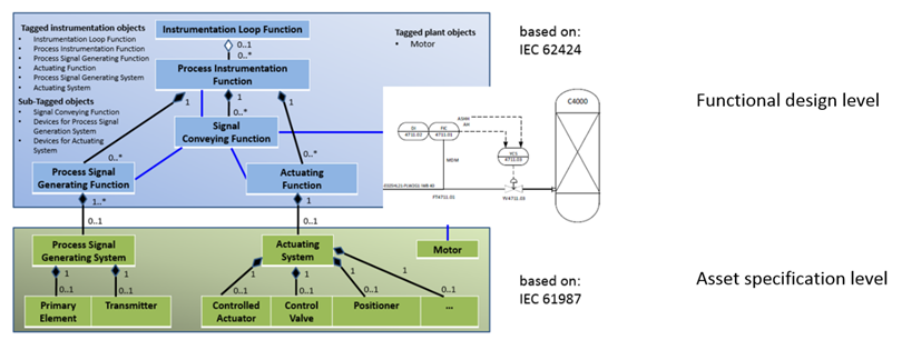
Figure 10 - A common information model compatible to all relevant instrumentation standards
The upper part of the model considers the functional concept, the lower one the device concept. The central functional object is the Process Instrumentation Function (in analogy to the concept PCE Request of the IEC 62424). Usually it is graphically shown with an instrumentation bubble. If required, Process Instrumentation Functions can be grouped in an Instrumentation Loop Function (PCE loop in IEC 62424). A use case for this is e.g. the definition of a local and at the same time central function like PI in which the pressure should be indicated in the field and also in the central operating room. Another use case is the multi sensor function D and F, in which a device should measure the density as well as the flow. A Process Instrumentation Function can have Process Signal Generating Functions as well as Actuating Functions as parts. Some standards have restrictions in this context, they permit either Process Signal Generating or Actuating Functions as parts. Regarding this issue, the DEXPI model is more comprehensive. Process Signal Generating and Actuating Functions are the objects which bundle up the functional demands for the sensing systems or actuating systems. In each case the property installation location, that at or in which object this function should be explained, is very important. The linking elements form the Signal Conveying Functions between the objects. All functional objects
- Instrumentation Loop Function,
- Process Instrumentation Function,
- Process Signal Generating Function and
- Actuating Function
have a unique identifier as a tag name. The DEXPI specification does not place any additional restrictions for naming conventions other than uniqueness, again to support as many different enterprise standards as possible. The device concept in the DEXPI model borrows very strongly from the IEC 61987 specification. Process Signal Generating and Actuating Systems (Composite Devices in IEC 61987) can have device components as parts. Some of these components are often shown on P&IDs graphically, for example, flow measuring instruments as sensor symbols as well as control valves and actuators. The model is extensible to other components. The Process Signal Generating System as well as the Actuating System are objects with unique identifiers within a plant. Their components are to be identified against it only within the scope of its use in the device group. The Process Signal Generating Systems must fulfill the demands of Process Signal Generating Functions, Actuating Systems the demands of the Actuating Functions. As a result, a bridge is built between the functional part and the device part in the model.
It is important to note that the engineering units and physical quantity types included to the DEXPI 1.2 specification document were not transferred to the OPC UA specification. The AnalogUnitType was used instead.