Overview
The Cutting Tools Information model specifies the OPC UA server of a tool manufacturing and a tool measuring machine implementation. Additionally, it describes the functionality of an OPC UA client application implementation. To make use of the functionalities described in this specification the OPC UA client application reads, writes, and calls methods on the respective servers. Annex B.2 therefore describes how a system architecture between machines and higher-level systems might be designed.
This deployment option describes that a cutting tool client application is running on both machines as well as in the higher-level IT system. The higher-level system client application uses the job management to facilitate the job management use case described in OPC 40001-3. Additionally, it puts the geometric data exchange file using the CuttingToolFileType as a work master on the tool manufacturing machine which is referenced in the job management. The tool measuring machine uses a separate client application to monitor the tool manufacturing machine job progress, reacting to the job completion and uses the work master file as an input for the measurement job commanded by the higher-level IT system. The tool manufacturing machine monitors the measuring machine again with a separate client application waiting for the nominal results of the measurement to facilitate the closed loop cutting tool manufacturing process.
The system architecture is shown schematically in Figure 8.
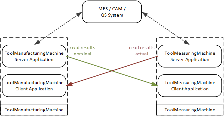
Figure 8 – System architecture with server and client on both machines
This deployment option describes that a cutting tool client application is running only in an external IT system. The higher-level system client application uses the job management to facilitate the job management use case described in OPC 40001-3. It stores and retrieves the files representing the work masters to the tool manufacturing machine and measuring machine using the CuttingToolFileType as a work master. Therefore, it is necessary to listen to state changes of the 6:ISA95JobResponseProviderObjectType of either machine to synchronize the jobs being carried out.
The system architecture is shown schematically in Figure 9.
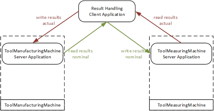
Figure 9 – System architecture with Server on both machines, controlled by an external client
This deployment option describes that a cutting tool client application synchronising manufacturing and measuring operations is running only on the tool manufacturing machine. The higher-level system client application uses the job management to facilitate the job management use case described in OPC 40001-3. It stores and retrieves the files representing the work masters to the tool manufacturing machine and measuring machine using the CuttingToolFileType as a work master. Furthermore, the client application running on the tool manufacturing machine facilitates the exchange of work master files between the tool manufacturing machine and measuring machine synchronizing the jobs being carried out. Alternatively, the synchronising client application could also run on the measuring machine.
The system architecture is shown schematically in Figure 10.
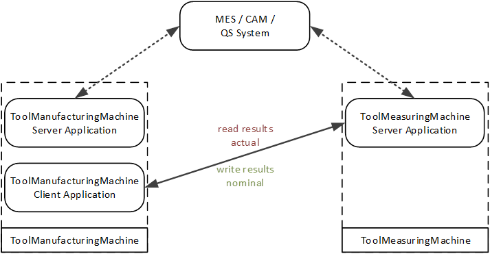
Figure 10 – System architecture with server on both machines and client on one machine
This deployment option shows the system architecture B.2.1 for the connection of multiple tool manufacturing machines with one measuring machine.
The system architecture is shown schematically in Figure 11.
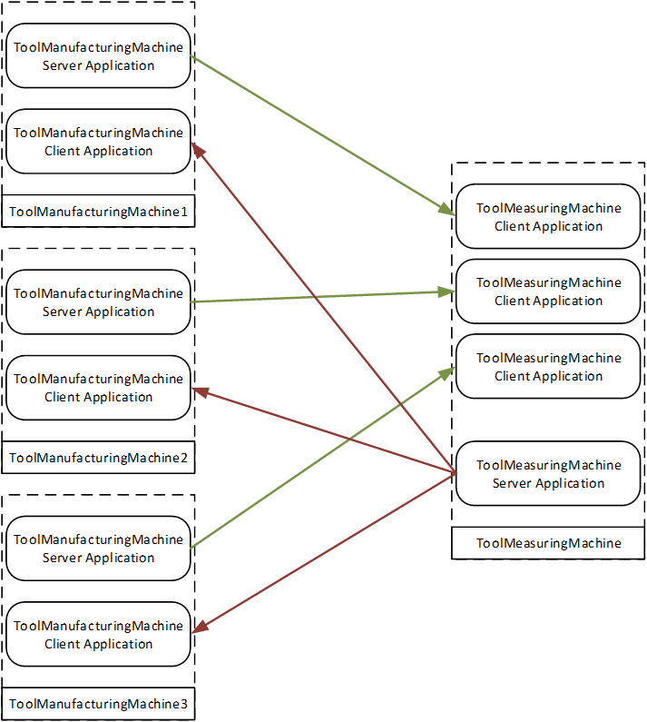
Figure 11 – System architecture for connection of multiple machines
___________