Errata exists for this version of the document.
The remainder of 4 defines the concepts of the AddressSpace. Clause 5 defines the NodeClasses of the AddressSpace representing the AddressSpace concepts. Clause 6 defines details on the type model for ObjectTypes and VariableTypes. Standard ReferenceTypes, DataTypes and EventTypes are defined in Clauses 7 to 9.
The informative Annex A describes general considerations on how to use the Address Space Model and the informative Annex B provides a UML Model of the Address Space Model. The normative Annex C defines a graphical notation for OPC UA data.
The primary objective of the OPC UA AddressSpace is to provide a standard way for Servers to represent Objects to Clients. The OPC UA Object Model has been designed to meet this objective. It defines Objects in terms of Variables and Methods. It also allows relationships to other Objects to be expressed. Figure 2 illustrates the model.
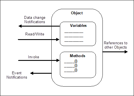
Figure 2 – OPC UA Object Model
The elements of this model are represented in the AddressSpace as Nodes. Each Node is assigned to a NodeClass and each NodeClass represents a different element of the Object Model. Clause 5 defines the NodeClasses used to represent this model.
The set of Objects and related information that the OPC UA Server makes available to Clients is referred to as its AddressSpace. The model for Objects is defined by the OPC UA Object Model (see 4.2).
Objects and their components are represented in the AddressSpace as a set of Nodes described by Attributes and interconnected by References. Figure 3 illustrates the model of a Node and the remainder of 4.3 discusses the details of the Node Model.
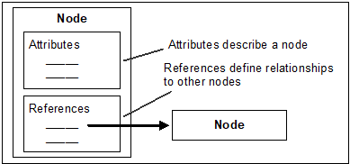
Figure 3 – AddressSpace Node Model
NodeClasses are defined in terms of the Attributes and References that shall be instantiated (given values) when a Node is defined in the AddressSpace. Attributes are discussed in 4.3.3 and References in 4.3.4.
Clause 5 defines the NodeClasses for the OPC UA AddressSpace. These NodeClasses are referred to collectively as the metadata for the AddressSpace. Each Node in the AddressSpace is an instance of one of these NodeClasses. No other NodeClasses shall be used to define Nodes, and as a result, Clients and Servers are not allowed to define NodeClasses or extend the definitions of these NodeClasses.
Attributes are data elements that describe Nodes. Clients can access Attribute values using Read, Write, Query, and Subscription/MonitoredItem Services. These Services are defined in OPC 10000-4.
Attributes are elementary components of NodeClasses. Attribute definitions are included as part of the NodeClass definitions in Clause 5 and, therefore, are not included in the AddressSpace.
Each Attribute definition consists of an attribute id (for attribute ids of Attributes, see OPC 10000-6), a name, a description, a data type and a mandatory/optional indicator. The set of Attributes defined for each NodeClass shall not be extended by Clients or Servers.
When a Node is instantiated in the AddressSpace, the values of the NodeClass Attributes are provided. The mandatory/optional indicator for the Attribute indicates whether the Attribute has to be instantiated.
References are used to relate Nodes to each other. They can be accessed using the browsing and querying Services defined in OPC 10000-4.
Like Attributes, they are defined as fundamental components of Nodes. Unlike Attributes, References are defined as instances of ReferenceType Nodes. ReferenceType Nodes are visible in the AddressSpace and are defined using the ReferenceType NodeClass (see 5.3).
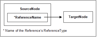
The Node that contains the Reference is referred to as the SourceNode and the Node that is referenced is referred to as the TargetNode. The combination of the SourceNode, the ReferenceType and the TargetNode are used in OPC UA Services to uniquely identify References. Thus, each Node can reference another Node with the same ReferenceType only once. Any subtypes of concrete ReferenceTypes are considered to be equal to the base concrete ReferenceTypes when identifying References (see 5.3 for subtypes of ReferenceTypes). Figure 4 illustrates this model of a Reference.
The TargetNode of a Reference may be in the same AddressSpace or in the AddressSpace of another OPC UA Server. TargetNodes located in other Servers are identified in OPC UA Services using a combination of the remote Server name and the identifier assigned to the Node by the remote Server.
OPC UA does not require that the TargetNode exists, thus References may point to a Node that does not exist.
Variables are used to represent values. Two types of Variables are defined, Properties and DataVariables. They differ in the kind of data that they represent and whether they can contain other Variables.
Properties are Server-defined characteristics of Objects, DataVariables and other Nodes. Properties differ from Attributes in that they characterise what the Node represents, such as a device or a purchase order. Attributes define additional metadata that is instantiated for all Nodes from a NodeClass. Attributes are common to all Nodes of a NodeClass and only defined by this specification whereas Properties can be Server-defined.
For example, an Attribute defines the DataType of Variables whereas a Property can be used to specify the engineering unit of some Variables.
To prevent recursion, Properties are not allowed to have Properties defined for them. To easily identify Properties, the BrowseName of a Property shall be unique in the context of the Node containing the Properties (see 5.6.3 for details).
A Node and its Properties shall always reside in the same Server.
DataVariables represent the content of an Object. For example, a file Object may be defined that contains a stream of bytes. The stream of bytes may be defined as a DataVariable that is an array of bytes. Properties may be used to expose the creation time and owner of the file Object.
For example, if a DataVariable is defined by a data structure that contains two fields, “startTime” and “endTime” then it might have a Property specific to that data structure, such as “earliestStartTime”.
As another example, function blocks in control systems might be represented as Objects. The parameters of the function block, such as its setpoints, may be represented as DataVariables. The function block Object might also have Properties that describe its execution time and its type.
DataVariables may have additional DataVariables, but only if they are complex. In this case, their DataVariables shall always be elements of their complex definitions. Following the example introduced by the description of Properties in 4.4.2, the Server could expose “startTime” and “endTime” as separate components of the data structure.
As another example, a complex DataVariable may define an aggregate of temperature values generated by three separate temperature transmitters that are also visible in the AddressSpace. In this case, this complex DataVariable could define HasComponent References from it to the individual temperature values that it is composed of.
OPC UA Servers shall provide type definitions for Objects and Variables. The HasTypeDefinition Reference shall be used to link an instance with its type definition represented by a TypeDefinitionNode. Type definitions are required; however, OPC 10000-5 defines a BaseObjectType, a PropertyType, and a BaseDataVariableType so a Server can use such a base type if no more specialised type information is available. Objects and Variables inherit the Attributes specified by their TypeDefinitionNode (see 6.4 for details).
In some cases, the NodeId used by the HasTypeDefinition Reference will be well-known to Clients and Servers. Organizations may define TypeDefinitionNodes that are well-known in the industry. Well-known NodeIds of TypeDefinitionNodes provide for commonality across OPC UA Servers and allow Clients to interpret the TypeDefinitionNode without having to read it from the Server. Therefore, Servers may use well-known NodeIds without representing the corresponding TypeDefinitionNodes in their AddressSpace. However, the TypeDefinitionNodes shall be provided for generic Clients. These TypeDefinitionNodes may exist in another Server.
The following example, illustrated in Figure 5, describes the use of the HasTypeDefinition Reference. In this example, a setpoint parameter “SP” is represented as a DataVariable in the AddressSpace. This DataVariable is part of an Object not shown in the figure.
To provide for a common setpoint definition that can be used by other Objects, a specialised VariableType is used. Each setpoint DataVariable that uses this common definition will have a HasTypeDefinition Reference that identifies the common “SetPoint” VariableType.
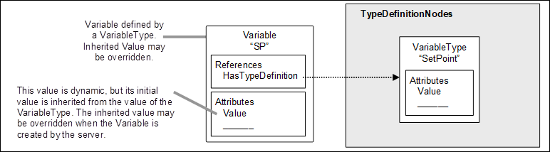
Figure 5 – Example of a Variable defined by a VariableType
TypeDefinitionNodes can be complex. A complex TypeDefinitionNode also defines References to other Nodes as part of the type definition. The ModellingRules defined in 6.4.4 specify how those Nodes are handled when creating an instance of the type definition.
A TypeDefinitionNode references instances instead of other TypeDefinitionNodes to allow unique names for several instances of the same type, to define default values and to add References for those instances that are specific to this complex TypeDefinitionNode and not to the TypeDefinitionNode of the instance. For example, in Figure 6 the ObjectType “AI_BLK_TYPE”, representing a function block, has a HasComponent Reference to a Variable “SP” of the VariableType “SetPoint”. “AI_BLK_TYPE” could have an additional setpoint Variable of the same type using a different name. It could add a Property to the Variable that was not defined by its TypeDefinitionNode “SetPoint”. And it could define a default value for “SP”, that is, each instance of “AI_BLK_TYPE” would have a Variable “SP” initially set to this value.
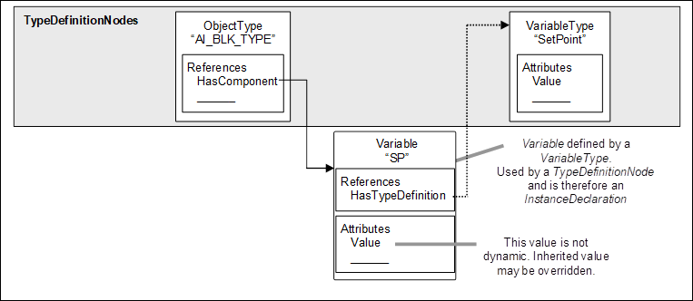
Figure 6 – Example of a Complex TypeDefinition
This approach is commonly used in object-oriented programming languages in which the variables of a class are defined as instances of other classes. When the class is instantiated, each variable is also instantiated, but with the default values (constructor values) defined for the containing class. That is, typically, the constructor for the component class runs first, followed by the constructor for the containing class. The constructor for the containing class may override component values set by the component class.
To distinguish instances used for the type definitions from instances that represent real data, those instances are called InstanceDeclarations. However, this term is used to simplify this specification, if an instance is an InstanceDeclaration or not is only visible in the AddressSpace by following its References. Some instances may be shared and therefore referenced by TypeDefinitionNodes, InstanceDeclarations and instances. This is similar to class variables in object-oriented programming languages.
This standard allows subtyping of type definitions. The subtyping rules are defined in Clause 6. Subtyping of ObjectTypes and VariableTypes allows:
- Clients that only know the supertype to handle an instance of the subtype as if it were an instance of the supertype;
- instances of the supertype to be replaced by instances of the subtype;
- specialised types that inherit common characteristics of the base type.
In other words, subtypes reflect the structure defined by their supertype but may add additional characteristics. For example, a vendor may wish to extend a general “TemperatureSensor” VariableType by adding a Property providing the next maintenance interval. The vendor would do this by creating a new VariableType which is a TargetNode for a HasSubtype reference from the original VariableType and adding the new Property to it.
The instantiation of complex TypeDefinitionNodes depends on the ModellingRules defined in 6.4.4. However, the intention is that instances of a type definition will reflect the structure defined by the TypeDefinitionNode. Figure 7 shows an instance of the TypeDefinitionNode “AI_BLK_TYPE”, where the ModellingRule Mandatory, defined in 6.4.4.5.2, was applied for its containing Variable. Thus, an instance of “AI_BLK_TYPE”, called AI_BLK_1”, has a HasTypeDefinition Reference to “AI_BLK_TYPE”. It also contains a Variable “SP” having the same BrowseName as the Variable “SP” used by the TypeDefinitionNode and thereby reflects the structure defined by the TypeDefinitionNode.
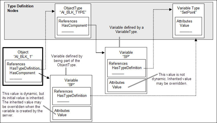
Figure 7 – Object and its Components defined by an ObjectType
A client knowing the ObjectType “AI_BLK_TYPE” can use this knowledge to directly browse to the containing Nodes for each instance of this type. This allows programming against the TypeDefinitionNode. For example, a graphical element may be programmed in the client that handles all instances of “AI_BLK_TYPE” in the same way by showing the value of “SP”.
There are several constraints related to programming against the TypeDefinitionNode. A TypeDefinitionNode or an InstanceDeclaration shall never reference two Nodes having the same BrowseName using forward hierarchical References. Instances based on InstanceDeclarations shall always keep the same BrowseName as the InstanceDeclaration they are derived from. A special Service defined in OPC 10000-4 called TranslateBrowsePathsToNodeIds may be used to identify the instances based on the InstanceDeclarations. Using the simple Browse Service might not be sufficient since the uniqueness of the BrowseName is only required for TypeDefinitionNodes and InstanceDeclarations, not for other instances. Thus, “AI_BLK_1” may have another Variable with the BrowseName “SP”, although this one would not be derived from an InstanceDeclaration of the TypeDefinitionNode.
Instances derived from an InstanceDeclaration shall be of the same TypeDefinitionNode or a subtype of this TypeDefinitionNode.
A TypeDefinitionNode and its InstanceDeclarations shall always reside in the same Server. However, instances may point with their HasTypeDefinition Reference to a TypeDefinitionNode in a different Server.
The Event Model defines a general purpose eventing system that can be used in many diverse vertical markets.
Events represent specific transient occurrences. System configuration changes and system errors are examples of Events. Event Notifications report the occurrence of an Event. Events defined in this document are not directly visible in the OPC UA AddressSpace. Objects and Views can be used to subscribe to Events. The EventNotifier Attribute of those Nodes identifies if the Node allows subscribing to Events. Clients subscribe to such Nodes to receive Notifications of Event occurrences.
Event Subscriptions use the Monitoring and Subscription Services defined in OPC 10000-4 to subscribe to the Event Notifications of a Node.
Any OPC UA Server that supports eventing shall expose at least one Node as EventNotifier. The Server Object defined in OPC 10000-5 is used for this purpose. Events generated by the Server are available via this Server Object. A Server is not expected to produce Events if the connection to the event source is down for some reason (i.e. the system is offline).
Events may also be exposed through other Nodes anywhere in the AddressSpace. These Nodes (identified via the EventNotifier Attribute) provide some subset of the Events generated by the Server. The position in the AddressSpace dictates what this subset will be. For example, a process area Object representing a functional area of the process would provide Events originating from that area of the process only. It should be noted that this is only an example and it is fully up to the Server to determine what Events should be provided by which Node.
Each Event is of a specific EventType. A Server may support many types. This part defines the BaseEventType that all other EventTypes derive from. It is expected that other companion specifications will define additional EventTypes deriving from the base types defined in this part.
The EventTypes supported by a Server are exposed in the AddressSpace of a Server. EventTypes are represented as ObjectTypes in the AddressSpace and do not have a special NodeClass associated to them. OPC 10000-5 defines how a Server exposes the EventTypes in detail.
EventTypes defined in this document are specified as abstract and therefore never instantiated in the AddressSpace. Event occurrences of those EventTypes are only exposed via a Subscription. EventTypes exist in the AddressSpace to allow Clients to discover the EventType. This information is used by a client when establishing and working with Event Subscriptions. EventTypes defined by other parts of this series of standards or companion specifications as well as Server specific EventTypes may be defined as not abstract and therefore instances of those EventTypes may be visible in the AddressSpace although Events of those EventTypes are also accessible via the Event Notification mechanisms.
Standard EventTypes are described in Clause 9. Their representation in the AddressSpace is specified in OPC 10000-5.
Events can be categorised by creating new EventTypes which are subtypes of existing EventTypes but do not extend an existing type. They are used only to identify an event as being of the new EventType. For example, the EventType DeviceFailureEventType could be subtyped into TransmitterFailureEventType and ComputerFailureEventType. These new subtypes would not add new Properties or change the semantic inherited from the DeviceFailureEventType other than purely for categorization of the Events.
Event sources can also be organised into groups by using the Event ReferenceTypes described in 7.16 and 7.18. For example, a Server may define Objects in the AddressSpace representing Events related to physical devices, or Event areas of a plant or functionality contained in the Server. Event References would be used to indicate which Event sources represent physical devices and which ones represent some Server-based functionality. In addition, References can be used to group the physical devices or Server-based functionality into hierarchical Event areas. In some cases, an Event source may be categorised as being both a device and a Server function. In this case, two relationships would be established. Refer to the description of the Event ReferenceTypes for additional examples.
Clients can select a category or categories of Events by defining content filters that include terms specifying the EventType of the Event or a grouping of Event sources. The two mechanisms allow for a single Event to be categorised in multiple manners. A client could obtain all Events related to a physical device or all failures of a particular device.
Methods are “lightweight” functions, whose scope is bounded by an owning (see Note) Object, similar to the methods of a class in object-oriented programming or an owning ObjectType, similar to static methods of a class. Methods are invoked by a client, proceed to completion on the Server and return the result to the client. The lifetime of the Method’s invocation instance begins when the client calls the Method and ends when the result is returned.
NOTE The owning Object or ObjectType is specified in the service call when invoking the Method.
While Methods may affect the state of the owning Object, they have no explicit state of their own. In this sense, they are stateless. Methods can have a varying number of input arguments and return resultant arguments. Each Method is described by a Node of the Method NodeClass. This Node contains the metadata that identifies the Method’s arguments and describes its behaviour.
Methods are invoked by using the Call Service defined in OPC 10000-4.
Clients discover the Methods supported by a Server by browsing for the owning Objects References that identify their supported Methods.
A Role is a function assumed by a Client when it accesses a Server. Roles are used to separate authentication (determining who a Client is) from authorization (determining what the Client is allowed to do). By separating these tasks Servers can allow centralized services to manage user identities and credentials while the Server only manages the Permissions on its Nodes assigned to Roles.
The set of Roles supported by a Server are published as components of the Roles Object defined in OPC 10000-5. Servers should define a base set of Roles and allow configuration Clients to add system specific Roles.
When a Session is created, the Server must determine what Roles are granted to that Session. This specification defines standard mapping rules which Servers may support. Servers may also use vendor specific mapping rules in addition to or instead of the standard rules.
The standard mapping rules allow Roles to be granted based on:
- User identity;
- Application identity;
- Endpoint;
User identity mappings can be based on user names, user certificates or user groups. Well known groups include ‘AuthenticatedUser’ (any user with valid credentials) and ‘Anonymous’ (no user credentials provided).
Application identity mappings are based on the ApplicationUri specified in the Client Certificate. Application identity can only be enforced if the Client proves possession of a trusted Certificate by using it to create a Secure Channel or by providing a signature in ActivateSession (see OPC 10000-4).
Endpoint identity mappings are based on the URL used to connect to the Server. Endpoint identity can be used to restrict access to Clients running on particular networks.
OPC 10000-5 defines the Objects, Methods and DataTypes used to represent and manage these mapping rules in the Address Space.
All Servers should support the well-known Roles which are defined in Table 2. The NodeIds for the well-known Roles are defined in OPC 10000-6.
|
BrowseName |
Suggested Permissions |
|
Anonymous |
The Role has very limited access for use when a Session has anonymous credentials. |
|
AuthenticatedUser |
The Role has limited access for use when a Session has valid non-anonymous credentials but has not been explicitly granted access to a Role. |
|
Observer |
The Role is allowed to browse, read live data, read historical data/events or subscribe to data/events. |
|
Operator |
The Role is allowed to browse, read live data, read historical data/events or subscribe to data/events. In addition, the Session is allowed to write some live data and call some Methods. |
|
Engineer |
The Role is allowed to browse, read/write configuration data, read historical data/events, call Methods or subscribe to data/events. |
|
Supervisor |
The Role is allowed to browse, read live data, read historical data/events, call Methods or subscribe to data/events. |
|
ConfigureAdmin |
The Role is allowed to change the non-security related configuration settings. |
|
SecurityAdmin |
The Role is allowed to change security related settings. |
When a Client attempts to access a Node, the Server goes through the list of Roles granted to the Session and logically ORs the Permissions for the Role on the Node. If there are no Node specific Permissions then the default Permissions for the Role in the DefaultRolePermissions Property of the NamespaceMetadata for the namespace the Node belongs to are used (see OPC 10000-5). The resulting mask is the effective Permissions. If the bits corresponding to current operation are set, then the operation can proceed. If they are not set the Server returns Bad_UserAccessDenied.
Roles appear under the Roles Object in the Server Address Space. Each Role has mapping rules defined which appear as Properties of the Role Object (see OPC 10000-5). The examples shown in Table 3 illustrate how the standard mapping rules can be used to determine which Roles a Session has access to and, consequently, the Permissions that are granted to the Session.
|
Role |
Mapping Rules |
Description |
|
Anonymous |
Identities = Anonymous Applications = Endpoints = |
An identity mapping rule that specifies the Role applies to anonymous users. |
|
AuthenticatedUser |
Identities = AuthenticatedUser Applications = Endpoints = |
An identity mapping rule that specifies the Role applies to authenticated users. |
|
Operator1 |
Identities = User with name ‘Joe’ Applications = urn:OperatorStation1 Endpoints = |
An identity mapping rule that specifies specific users that have access to the Role with a application rule that restricts access to a single Client application. |
|
Operator2 |
Identities = Users with name ‘Joe’ or ‘Ann’ Applications = urn:OperatorStation2 Endpoints = |
An identity mapping rule that specifies specific users that have access to the Role with a application rule that restricts access to a single Client application. |
|
Supervisor |
Identities = User with name ‘Root’ Applications = Endpoints = |
An identity mapping rule that specifies specific users that have access to the Role |
|
Administrator |
Identities = User with name ‘Root’ Applications = Endpoints = opc.tcp://127.0.0.1:48000 |
An identity mapping rule that specifies specific users that have access to the Role when they connect via a specific Endpoint. |
The examples also make use of the Nodes defined in Table 4. The table specifies the value of the RolePermissions Attribute for each Node.
|
Node |
Role Permissions |
|
Unit1.Measurement |
AuthenticatedUser = Browse Operator1 = Browse, Read |
|
Unit2.Measurement |
AuthenticatedUser = Browse Operator2 = Browse, Read |
|
SetPoint |
AuthenticatedUser = Browse Operator1 and Operator2 = Browse, Read, Write Supervisor = Browse, Read |
|
DisableDevice |
AuthenticatedUser = Browse Operator1 and Operator2 = Browse, Read Administrator = Browse, Read, Write |
When a Client creates a Session the Roles assigned to the Session depend on the rules defined for each Role. Table 5 lists the assigned Roles for different Sessions created with different Users, Client applications and Endpoints.
Table 5 – Example Role Assignment
|
User Provided by Client |
Roles Assigned to Session |
|
Anonymous |
Anonymous |
|
Sam |
AuthenticatedUser |
|
Joe using OperatorStation1 application. |
AuthenticatedUser, Operator1 |
|
Joe using OperatorStation2 application. |
AuthenticatedUser, Operator2 |
|
Joe using generic application. |
AuthenticatedUser |
|
Root using OperatorStation1 application. |
AuthenticatedUser, Supervisor |
|
Root using generic application and 127.0.0.1 endpoint. |
AuthenticatedUser, Supervisor, Administrator |
|
Root using generic application and another endpoint. |
AuthenticatedUser, Supervisor |
When a Client application accesses a Node the RolePermissions for the Node are compared to the Roles assigned to the Session. Any Permissions available to at least one Role is granted to the Client. Table 6 provides a number of scenarios and examples and the resulting decision on access.
Table 6 – Examples of Evaluating Access
|
Use Case |
Role Permissions |
|
Anonymous user on localhost browses Unit1.Measurement Node. |
Access denied because no rule defined for Anonymous users. |
|
User ‘Sam’ using OperatorStation1 application browses Unit1.Measurement Node. |
Allowed because AuthenticatedUser is granted Browse Permission. |
|
User ‘Sam’ using OperatorStation2 application reads Value of Unit1.Measurement Node. |
Access denied because AuthenticatedUser is not granted Read Permission. |
|
User ‘Joe’ using OperatorStation1 application reads Value of Unit1.Measurement Node. |
Allowed because Operator1 is granted Read Permission. |
|
User ‘Joe’ using OperatorStation2 application reads Value of Unit1.Measurement Node. |
Access denied because AuthenticatedUser and Operator2 are not granted Read Permission. |
|
User ‘Joe’ using generic OPC UA application reads Value of Measurement Node. |
Access denied because AuthenticatedUser is not granted Read Permission. |
|
User ‘Joe’ using OperatorStation1 application write Value of SetPoint Node. |
Allowed because Operator1 is granted Write Permission. |
|
User ‘Root’ using OperatorStation1 application write the Value of SetPoint Node. |
Denied because AuthenticatedUser and Supervisor are not granted Write Permission. |
|
User ‘Joe’ using OperatorStation1 application write Value of DisableDevice Node. |
Access denied because AuthenticatedUser and Operator1 are not granted Write Permission. |
|
User ‘Root’ using OperatorStation1 application write the Value of DisableDevice Node. |
Access denied because AuthenticatedUser and Supervisor are not granted Write Permission. |
|
User ‘Root’ using endpoint 127.0.0.1 to write Value of DisableDevice Node. |
Allowed because Administrator is granted Write Permission. |