The following use cases illustrate the usage of the information model. Not all necessary Objects must be realized within a concrete OPC UA Server. These use cases cover a system that is BACnet client and OPC UA server. The use cases for the other direction (OPC UA client and BACnet server) are not covered in the current version and may be added in a future version.
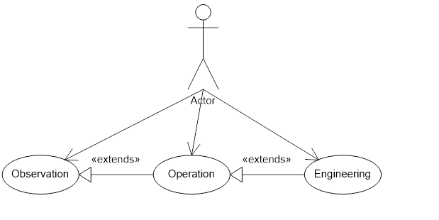
- Observation
Observation comprises reading and monitoring data such as present value, trend log and events of BACnet objects available in an existing BACnet network from a BACnet OPC UA Server.
The representation of BACnet internetworks, devices their objects and properties is consistent across BACnet OPC UA server products.
The BACnet OPC UA server may restrict the exposed information from a BACnet internetwork through configuration and/or user autorization.
Example 1: Enterprise integration (monitoring energy consumption, comparing trends)
Example 2: Multi domain integration (building automation with industrial automation)
- Operation
Operation inherits the functionality of observation and extends it.
Operation comprises writing data such as set points, selecting mode of operation or acknowledge alarms through the BACnet OPC UA server.
Example 1: Enterprise integration (writing set points)
Example 2: Multi domain integration (building automation with industrial automation) (writing operation mode)
- Engineering (Configuration / Maintenance)
Engineering inherits the functionality of operation and extends it.
Engineering comprises of configuring BACnet objects through a BACnet OPC UA Server like configuring modes of operation, enabling/disabling alarms and configuring schedules.
Example1: The properties of BACnet devices may be configured by OPC UA clients during the installation or engineering phase.
Example2: If room assignments or names change, the object representation may need to be updated accordingly. The OPC UA mapping model may be used to access and modify this information.
The following Figure 4 shows the use case diagram.