Use cases in this document are described in tables to have a unified representation. These tables contain the following rows:
- Goal:The objective of the use case.
- Implements:Relation to the corresponding requirement.
- Preconditions:One or more conditions which must be met as a precondition for the use case.
- OPC UA mapping:This section describes the behavior of the use case by an OPC UA viewpoint.
The following asset management use-cases focus mainly on running applications and plants. During the commissioning phase changes in the assets are normal. The asset management phase begins after the acceptance tests of the commissioning phase.
The following chapters give a brief introduction to relevant PROFINET objects and services, which are used in the scope of the OPC UA integration use cases. A detailed definition of these terms can be found in documents from Chapter 2 or several printed documents which are available at www.profinet.com. Nevertheless, the reader of this document should be able to understand the basic PROFINET concepts without knowledge of all the details.
It is important, that the support of some PROFINET information below is not mandatory. Therefore, an optimal usability and features coverage can be achieved with devices which implement a maximum of optional PROFINET features. The requirement of the PROFINET specification is denoted by the capital (PN-M) for mandatory or (PN-O) for optional.
The following information is general for all PROFINET devices.
- Device Information (PN-M):Information that is related to the device with the PROFINET connection to the network. Examples are VendorID, DeviceID, DCP type identification, DNS Name of Station and IP-Address.
- Physical Topology (PN-M):PROFINET can discover the physical topology of installed devices as all devices exchange neighborhood information with the LLDP protocol.
- Real Configuration (PN-M):The real configuration of a PROFINET device contains slots and subslots with modules and submodules plugged in the device independent from any controller connection. Each module/submodule is identified by a module/submodule identification number which must be unique in the scope of one DeviceID. One defined submodule is the representative of the device; one submodule is the representative of a module. Therefore, the submodule is the carrier of all information. Modules and submodules which are installed in the real configuration of the device can be discovered with a PROFINET service. These modules/submodules are the carrier of the asset information.
- Expected Configuration (PN-M):The expected PROFINET configuration is the result of the PROFINET engineering in the configuration tool of the PLC. It contains the devices, modules, submodules which are configured in the engineering system of the PLC, downloaded to the controller and transferred to the devices during startup.The expected configuration can be read with a defined PROFINET service.
- Module Diff Block (PN-M):The difference between the expected configuration and the real configuration. The reference to the difference is the expected configuration. The module diff block can be read with a defined PROFINET service.
PROFINET defines Identification and Maintenance functions since PROFIBUS. As there is a long history, some restrictions in these data are possible. In general, I&M contain defined properties and values to identify the asset more precise as it is possible with IDs and without knowledge of the GSD file.
- I&M0 – Electronic Faceplate (PN-M for device, PN-O for Modules):Version Information of the submodule like serial number, HW-Version and FW-Version. I&M0 data are read-only.
- I&M1 – function and location (PN-O):A unique function and location of the device/submodule as visible strings. I&M1 data must be written by a PROFINET engineering tool or PLC before they can be used. The mapping to marking systems like IEC 81346 are in the responsibility of the user and not in scope of this document.
- I&M2 – comment (PN-O):A comment to the device as visible string. I&M2 data must be written by a PROFINET engineering tool or PLC before they can be used.
- I&M3 – installation date (PN-O):The installation date of the device. I&M3 data must be written by a PROFINET engineering tool or PLC before they can be used.
- I&M4 – signature (PN-M and defined for Functional Safety):If the submodule is configured by an external safety configuration tool, this tool can write a signature of the parameter set in I&M4 data of the submodule. With its signature it is possible to discover differences between a stored parameter set of the engineering tool and a parameter set in the field. I&M4 is only defined for safety devices.
- I&M5 – additional information (PN-O)Offers additional information about a communication module which is part on an IO device. If the device (e.g. a robot) is made by company A, and the communication module by company B, I&M0 contain information about the robot and company A, I&M5 contain information about the communication module and company B.
In addition to the above I&M data which are only bound to the PROFINET address elements slot/subslot, additional end customer requirements for enhanced asset management capabilities are incorporated in the PROFINET specification. Definition of PROFINET asset management objects sometimes use data types already defined by I&M properties. In addition to them other asset management properties are available. Asset information can be bound to slots and subslots to extend information, which cannot be modelled with I&M properties. Moreover, the PROFINET specification defines a level-tree of assets which objects are independent from the slot/subslot addressing scheme.
The following picture shows a possible example of asset management usage in a modular IO device.
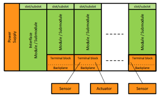
Figure 11 – Asset management example modular IO
The green elements are the modules and submodules of the station carrying I&M information. Additional asset information like version info of the power supply, terminal blocks or connected sensors and actors can be described by means of asset management objects, which are not directly related to the slot/subslot model.
In addition to this example PROFINET AM can be used to manage all components with loadable software, which can be device or module firmware as well as application programs running on PLCs or robots.
The following asset management objects can be accessed via a defined acyclic read service.
- AM_Info:The scope of the asset information, which can be “full information”, “firmware only” or “hardware only”.
- AM_Location:The location of an asset within a device as 16 subsequent octets. The location can be either “slot/subslot” to extend I&M information or “level tree” to form hierarchical structures of assets.
- IM_UniqueIdentifier:A 128-bit globally unique identification of the asset created by the manufacturer e.g. by means of ISO/IEC 9834-8:2014.
- IM_Annotation:A manufacturer-specific identifier of the asset such as the asset’s name as Unicode string8 with the length of 64 octets.
- IM_OrderID:The order ID of the asset as UnicodeString8 with the length of 64 octets.
- AM_SoftwareRevision:The edition of the software of the asset as UnicodeString8 with 64 octets.
- IM_Software_Revision:Software revision in a special I&M coding of VisibleString[9].
- AM_HardwareRevision:The edition of the hardware of the asset as UnicodeString8 with 64 octets.
- IM_Hardware_RevisionThe hardware revision in I&M coding.
- IM_Serial_Number:A unique production number of the asset set by the manufacturer as VisibleString16.
- AM_DeviceIdentification:The unique device identification in the address space of an organization like VendorID & DeviceID for PI. Or OUI for IO-Link.
- AM_TypeIdentification:Used to identify the family of the asset and assigned by the manufacturer like “IO controller”, “IO device”, “IO-Module”. Standard and manufacturer specific values are defined in [3].
The architecture from Chapter 5.2.1 can be specialized for the usage within asset management. An asset management tool as OPC UA Client is connected to an OPC UA Server located in a PLC, Edge gateway or IO device. The PLC acts as IO controller for the underlying PROFINET system. The Edge gateway is scanning the underlying assets by means of DCP and implicit Read Services.
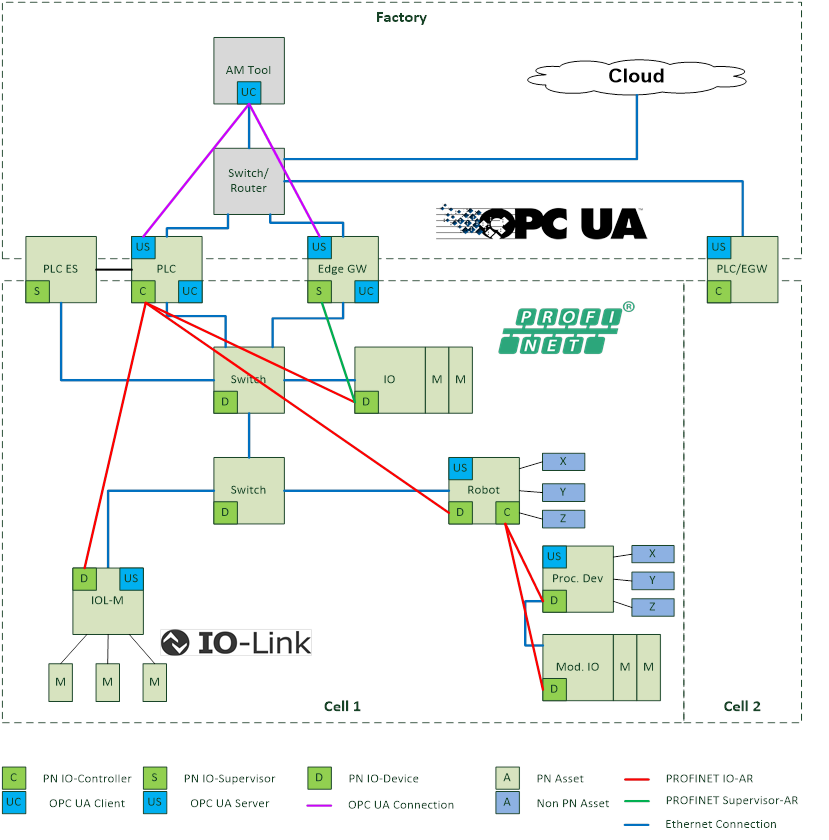
Figure 12 – Architecture of Asset Management
The following end customer requirements are relevant for asset management. A more detailed description of these use cases can be found in [PN TAD].
The requirements are written from the perspective of an asset management tool user.
Table 8 – Asset Management User Requirements
|
ID |
Name |
Details |
|
AM1 |
Unique Identification |
The asset must have a unique Identification in the namespace of all installed assets independent whether the asset is installed in a cell or a machine. |
|
AM2 |
Hardware and Firmware version management |
Hardware and Firmware versions of the installed equipment should be discovered or compared with possible white-lists or black-lists. |
|
AM3 |
Application version management |
The application programs running on PLCs, robots or drives are also versioned and part of the asset management. Versioning for these applications shall be visible. This requirement can be solved in a comparable way then firmware version management. |
|
AM4 |
Asset changed |
End users want to know, if an asset is changed. |
|
AM5 |
Asset installed |
A new asset is installed in the cell or machine. |
|
AM6 |
Asset removed |
A new asset is removed from the cell or machine. |
|
AM7 |
Asset localization changed |
The physical location of an asset was changed. E.g. moved from one machine to another. |
|
AM8 |
Machine part discovery |
Usually the assets installed in a machine are in the responsibility of the machine builder. If some of these assets are replaced by the operator of a machine, the asset discovery of integrated assets is required. |
|
AM9 |
PROFIsafe Device parameters changed |
The OEM wants to know, if PROFIsafe Device parameters are changed by an external engineering tool in the device and/or in the engineering system of the IO controller for startup parameters. |
|
AM10 |
Asset location changed |
The asset is moved to a different place in the asset hierarchy. |
|
AM11 |
I&M Write |
The OEM wants to set writeable I&M1...3 parameters via OPC UA independent from the configuration in the engineering system of the IO controller. |
|
AM12 |
Network parameter check |
The end user wants to know, if all installed PROFINET devices follow specific rules for their network parameters given by the OEM. Network parameters are:
|
|
AM13 |
Docking Devices |
PROFINET devices which are connected and disconnected to the network at runtime in normal operation. |
The following use case describes the discovery of installed PROFINET assets.
Table 9 – Use case - Asset Discovery
|
Goal |
The end user wants to discover all installed assets within a cell. All available information shall be discovered. |
|
Implements |
AM1, AM8, AM12 |
|
Preconditions |
All PROFINET components are configured and connected to the network. Station Names and IP-Addresses of the devices can be set. The Tag-Function and Tag-Location in I&M1 and asset management data are available. The PLC/Edge Gateway is scanning the underlying network continuously with DCP-Identify and PROFINET read services to get all relevant asset information. For details see [1]. |
|
OPC UA Mapping |
AM tool connects the OPC UA Server in the EGW/PLC/Device. The OPC UA information model in the EGW is built based on the found devices, modules and submodules of the last scan cycle. The required I&M and Asset information are read with the corresponding PROFINET services in the context of an implicit or device access AR. The OPC UA information model in a PLC is built corresponding to the real configuration downloaded from the engineering system of the PLC. The required I&M and Asset information are read with the corresponding PROFINET services in the context of the already established IO-AR. The OPC UA information model in a device is build corresponding to the real configuration plugged by the local device application. The required I&M and Asset information are implemented according the local device application. |
|
Remarks |
When there is no station name, the MAC address shall be used as BrowseName. If those devices get a correct name, they are visible as a different entity under their station name as the OPC UA browse name shall be unique. |
The following chapter describes criteria to detect changes in the assets. They may be useful to implement corresponding functionalities in the asset management tool.
The user wants to be informed if assets in the plant or machine were changed. The following table describes criteria to detect changes.
Implements AM4.
Table 10 – Criteria for asset information changed
|
Changed asset |
Criteria |
PROFINET Service |
|
Device |
Software Version changedAKZ/OKZ changed |
I&M0:SoftwareVersion I&M1: AKZ/OKZ |
|
ModuleSubmodule |
Software Version changedAKZ/OKZ changed |
I&M0:SoftwareVersion I&M1: AKZ/OKZ |
|
Asset |
Software Version changedAKZ/OKZ changed |
Will be part of a next version of the companion specification |
The user wants to be informed if assets in the plant or machine were changed. The following table describes criteria to detect changes.
Implements AM4.
Table 11 – Criteria for asset exchange
|
Changed asset |
Criteria |
PROFINET Service |
|
Device |
Serial number changed |
IM_SerialNumber of the DAP |
|
ModuleSubmodule |
Serial number changed |
IM_SerialNumber of the module/submodule |
|
Asset |
Serial number changed |
IM_SerialNumber of the asset |
The user wants to be informed if assets in the plant or machine were added. The following table describes criteria to detect changes.
Implements AM5.
Table 12 – Criteria for added assets
|
Added asset |
Criteria |
PROFINET Service |
|
Device |
Device with unknown MAC address in the network |
DCP-Identify-All |
|
ModuleSubmodule |
Real configuration contains a new module/submodule |
RecordRead RealIdentificationData for all API’s |
|
Asset |
Asset list contains a new entry |
RecordRead AM_Info |
The user wants to be informed if assets in the plant or machine were removed. The following table describes criteria to detect changes.
Implements AM6.
Table 13 – Criteria for asset removal
|
Removed asset |
Criteria |
PROFINET Service |
|
Device |
Device list smaller than previous scan |
DCP-Identify-All |
|
ModuleSubmodule |
Real configuration contains less modules/submodules |
RecordRead RealIdentificationData for all API’s |
|
Asset |
Asset list contains less modules/submodules |
RecordRead AM_Info |
Special cases in PROFINET are devices which are connected and disconnected to the network at runtime, like devices installed on a tool gripped by a robot. It is not guaranteed, that docking devices can be fully discovered by the scan cycle of Edge gateways. An IO controller may show information of docking devices in the local OPC UA Server.
One important use case of asset management is the detection of firmware updates in the plant or machine as well as a version change in a programmable application running on a PLC, robot or drive. The following table describes criteria to detect changes.
Implements AM2, AM3.
Table 14 – Criteria for firmware or application program update
|
Updated asset |
Criteria |
PROFINET Service |
|
Device |
IM_SoftwareRevision of the submodule representing the device has a changed value. |
RecordRead I&M0FilterDataRecordRead I&M0 |
|
ModuleSubmodule |
IM_SoftwareRevision of module/submodule has a changed value. The modules/submodules with explicit I&M data can be found asking for I&M0FilterData. |
RecordRead I&M0FilterDataRecordRead I&M0 |
|
Asset |
IM_SoftwareRevision or AM_SoftwareRevision of asset has a changed value |
RecordRead AM_Info |
Sometimes it is important to know, if a safety parameter of a device in the plant or machine, set by an engineering tool, was changed. The following table describes criteria to detect changes.
Implements AM9.
Table 15 – Criteria for safety device parameter change
|
Changed Parameter |
Criteria |
PROFINET Service |
|
Device |
IM_Signature of DAP has a changed value |
RecordRead I&M4 |
|
ModuleSubmodule |
IM_ Signature of module/submodule has a changed value |
RecordRead I&M4 |
|
Asset |
Not available |
|
As special case for asset management is a change of a device in the physical topology. This is sometimes the case while finding errors in the field by exchange of devices.
Implements AM10.
Table 16 – Criteria for topology change
|
Topology change |
Criteria |
PROFINET Service |
|
Device moved |
Changed neighborhood information of a device with a known MAC address and/or SerialNumber |
DCP_IdentifiyRecordRead PDRealData |
|
Device added |
Device with an unknown MAC address in physical topology |
DCP_IdentifiyRecordRead PDRealData |
|
Device removed |
New physical topology without a device which was there before |
DCP_IdentifiyRecordRead PDRealData |
PROFINET defines a comprehensive diagnostic model. The main focuses of this model are device diagnosis and network diagnosis. Diagnosis scenarios can appear during startup of a plant as well as during operation.
Details of the PROFINET diagnosis concepts are contained in [PN Diag]. The main ideas are summarized in this chapter:
Figure 13 – Diagnosis base model from [PN Diag]
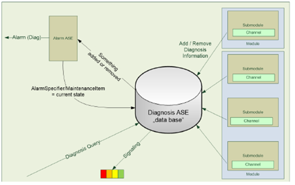
Each IO device maintains a global list of active diagnosis in a database called Diagnosis ASE.
All diagnosis entries are related to a channel of a submodule. The channel can represent a connected sensor or actor as well as the whole submodule. Submodule related diagnosis is marked with the channel number 0x8000.
If some relevant diagnosis or maintenance appears or disappears on a channel, an entry in the diagnosis ASE is added or removed. In this case, the IO controller is informed with diagnosis alarm to have event driven diagnosis information available in the PLC.
A supervisor like an Edge gateway or diagnosis tool can query the diagnosis ASE with a defined PROFINET record. If the ASE contains entries, the query is answered with a list of diagnosis entries. Otherwise the answer is empty to reduce the network load.
Figure 14 – Severity classification of diagnosis from [PN Diag]
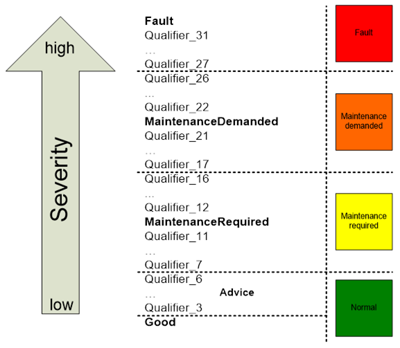
Each channel diagnosis entry contains a severity and a combination of error codes (see Figure 14). Some of these codes are system defined and can be decoded with the help of a general XML file available via PI. Vendor specific and profile specific error codes can be contained in the GSD file of the device.
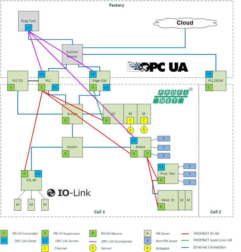
Figure 15 – Architecture of Diagnosis
In the Diagnosis Use-Case a diagnosis tool is connected to a PLC, Edge gateway or the OPC UA Server of the device itself. The integrated OPC UA Server represents the subordinate PROFINET system or devices and their diagnosis state. There are differences in the available diagnosis information in IO controllers, Edge gateways or devices, which must be considered:
- IO controllerAn IO controller may form an OPC UA object model which is based on the expected configuration given by the engineering system. If there is no PROFINET connection (IOAR) between the controller and the device, the controller knows the reason (e.g. Device not found, duplicated names in the network, etc.). IO controllers are informed from the devices with a diagnosis alarm, if anything in the diagnosis ASE has been changed and may determine a time accurate diagnosis state.
- Edge gateways:An Edge gateway may show IO controllers and IO devices which can be discovered during the scanning process. An Edge gateway may determine the expected configuration of the devices with a normative record. The reason for an e.g. unreachable device can be different from an IO controller. Supervisors like Edge Gateways are not informed with an alarm if something in the diagnosis ASE of the devices has been changed. They can be as time accurate as the scanning time is configured.
- Devices:The IO device represents the diagnosis state of the included modules and submodules. In addition it knows if there is a running AR to the IO controller.
Table 17 – Discover differences
|
Goal |
The end user wants to know if there are any differences between the expected configuration given in the ES of an IO controller and installed devices in the field. |
|
Preconditions |
The expected PROFINET configuration is set up in the engineering system of the IO controller, downloaded and activated. The Tag-Function and Tag-Location of I&M1 is configured. |
|
OPC UA Mapping |
In a PLC the information model of the OPC UA Server is build according the expected configuration of the PLCs engineering system. Differences between real and expected configuration are marked at the corresponding submodule of the expected configuration. In an EGW the information model of the OPC UA Server is build according to the scanned devices. Differences to the expected configuration are shown based on module diff block information read from the device. In a device the information model of the OPC UA Server is build according the local configuration. Differences to the expected configuration are shown based on module diff block from the controller AR. PLC is named with its station name and IP-Address. Devices are named with their station name, IP-Address and I&M1 information. |
Table 18 – Discover reachable configuration
|
Goal |
The end user wants to know which devices and their configuration are installed in the field. |
|
Preconditions |
All connected PROFINET systems are configured and running. There can be multiple PLCs in the network visible by an EGW. An EGW or PLC may scan the underlying network continuously with DCP-Identify and PROFINET read services to get all relevant information. For details see [PN TAD]. |
|
OPC UA Mapping |
The information model of the OPC UA Server is build according the scanned devices and their real slot/subslot configuration. This Use-Case should not be implemented in a Device to avoid network load caused by Identify services. |
|
Remarks |
When there is no station name, the MAC address shall be used as BrowseName. If those devices get a correct name, they are visible as a different entity under their station name as the OPC UA browse name shall be unique. |
Table 19 – Connection Diagnosis
|
Goal |
The end user wants to know the state of the PROFINET connections related to the expected configuration of the IO controller |
|
Preconditions |
The expected PROFINET configuration is set up in the engineering system of the IO controller, downloaded and activated. Some ARs between the IO controller and IO devices are established, others cannot be established by e.g. following reasons: Device with configured NoS not found in the network Duplicate NoS detected Duplicate IP-Address detected AR deactivated in PLC application program |
|
OPC UA Mapping |
The connection state of the AR is signaled on the corresponding IO device in the address space of the OPC UA Server. The reason for error is part of the AR. |
Table 20 – Submodule state diagnosis
|
Goal |
The end user wants to know differences between the expected and real configuration related to modules/submodules, their identification as well as other reasons for connection problems. |
|
Preconditions |
The expected PROFINET slot/subslot configuration is set up in the engineering system of the IO controller, downloaded and activated. An EGW may continuously scan the ExpectedConfiguration and ModuleDiffBlock data records from the reachable devices. Some submodules in real configuration differ from the expected. Details see SubmoduleState. Examples: Wrong Submodule No Submodule Substitute Submodule Application Ready Pending Superordinated Locked Locked by IO controller Locked by IO supervisor |
|
OPC UA Mapping |
The difference related to the expected configuration is signaled on the corresponding module/submodule in the address space of the UA Server. The state is shown in a variable with corresponding values of SubmoduleState. |
Table 21 – Device diagnosis or maintenance update
|
Goal |
The end user wants to have information about device/module/submodule/channel related diagnosis or maintenance information. |
|
Preconditions |
All connected PROFINET systems are configured and running. Channel related diagnosis or maintenance (e.g. short circuit) appears on one channel of a real or PDev submodule. An entry in the diagnosis ASE of the IO device is made. The IO controller is informed with a corresponding diagnosis or maintenance alarm. The EGW may scan the underlying network continuously with DCP-Identify and PROFINET read services to the diagnosis ASE. Channel related diagnosis or maintenance (e.g. short circuit) disappears on one channel of a real or PDev submodule. |
|
OPC UA Mapping |
The diagnosis or maintenance is signaled on the corresponding module or submodule in the address space of the OPC UA Server with the following information: ChannelNumber (0x8000 is the whole submodule itself) Severity: fault, maintenance required, maintenance demanded mapped to OPC UA severity classes Error Text from GSDML in current language. Formatted information of ExtChannelAddValue based on GSDML. + Help Text from GSDML.
|
Table 22 – Network diagnosis or maintenance
|
Goal |
The end user wants to have information about the “health” of the physical PROFINET network in the Diagnosis tool in a topological view. |
|
Preconditions |
All connected PROFINET systems are configured and running. PDev related diagnosis or maintenance appear on the network. An EGW or PLC may scan the underlying network continuously with DCP-Identify and PROFINET read services to get all relevant information. The PDev related diagnosis and properties are integrated in the OPC UA address space of the EGW or PLC according to Table 21. |
|
OPC UA Mapping |
A diagnosis tool uses the PDev related information from the OPC UA Server to display a topological view with corresponding details. It is not the responsibility of the OPC UA Server. |
|
Remark |
Display of physical Topology is possible for PROFINET-Devices and PROFINET-switches, but not possible for devices without topology information. |
This use case describes the reading and writing of PROFINET records via objects in the OPC UA Server. This use case is intentionally not provided in this companion specification because access to low level data records is a potential security problem and the access to additional application data via the OPC UA Server shall be done in a high-level object-oriented access.