PROFINET is the communication standard for automation from PROFIBUS & PROFINET International (PI). Its modular range of functions makes PROFINET a flexible system for all applications and markets. PROFINET is the networking solution of production and process automation, from applications with functional safety requirements and the entire spectrum of drive technology to isochronous motion control applications. The use of application profiles allows optimal usage of PROFINET in all areas of automation engineering.
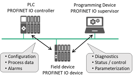 PROFINET follows the provider/consumer model for data exchange. This means that both the IO controller and IO device spontaneously send cyclic data independently. The following device classes are defined for PROFINET (Figure 1):
Figure 1 – Communication paths for PROFINET
IO controller: This is typically the Programmable Logic Controller (PLC) in which the automation program runs. The IO controller provides output data to the configured IO devices in its role as provider and is the consumer of input data.
IO device: An IO device is a distributed IO field device connected to one or more IO controllers via PROFINET. The IO device is the provider of input data and the consumer of output data from the IO controller.
IO supervisor: This can be a programming device (PG), personal computer (PC) or human machine interface (HMI) device for commissioning or diagnostic purposes.
A system unit contains at least one IO controller and one or more IO devices. IO supervisors are usually integrated only temporarily for commissioning or troubleshooting purposes.
In its logical structure, a PROFINET field device is always modular in design. Modularity in the logical sense, however, does not require actual modularity in the electrical and mechanical design sense. An IO device is usually comprised of a communication module with Ethernet interface and (physical or virtual) modules assigned to it. The assigned modules handle the actual process data traffic. The access point for communication (Ethernet interface with data processing) is called the DAP (Device Access Point). The following structures are standardized for an IO device:
- The device model consists of slots, subslots, modules and submodules.
- The slot designates the insertion slot of a module in an IO field device. A field device usually has two or more slots.
- A module is comprised of one or more submodules or provides available subslots into which submodules can be inserted.
- The modules themselves have no task other than to provide structuring. The actual inputs and outputs (channels) are implemented in its submodules. The granularity of the channels (bitwise, bytewise or wordwise division of IO data) is determined by the manufacturer. Acyclic services always address submodules. Therefore, a module always contains at least one submodule.
- The data content of a submodule is always accompanied by status information. The index specifies the data within a submodule inserted into a slot/subslot which can be read or written acyclically using read/write services. For example, parameters can be written to a module, or manufacturer-specific module data can be read out based on an index. Specific indexes are defined in the standard here. Additional indexes can be freely defined by the manufacturer.
The submodule is the owner of the user data, diagnostics, channels, actual configuration, records and I&M data. Cyclic IO data of the submodule in the device is addressed by specifying the slot/subslot combination of the insertion slot. They can be freely defined by the manufacturer. For acyclic data communication via read/write services, an application can specify the data of the submodule to be addressed using slot, subslot and index (Figure 2).
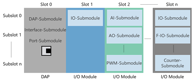
Figure 2 – Addressing of IO data in PROFINET based on slots and subslots
To establish communication between the higher-level controller and an IO device, the communication paths must be established. These are set up by the IO controller during system startup based on the configuration data received from the engineering system. This specifies the data exchange explicitly.
All data exchange is embedded into an AR (Application Relationship) (Figure 3). Within the AR, CRs (Communication Relationships) specify the data explicitly. As a result, all data for device modelling, including the general communication parameters, are downloaded to the IO device. An IO device can have multiple ARs established from different IO controllers, for example, for shared devices.
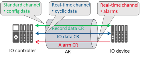
Figure 3 – Addressing of IO data in PROFINET based on slots and subslots
The communication channels for cyclic data exchange (IO data CR), acyclic data exchange (record data CR) and alarms (alarm CR) are set up simultaneously. Multiple IO controllers can be used in a PROFINET system (Figure 4). If these IO controllers can access the same data in the IO devices, this must be specified during parameter configuration (shared devices and shared inputs).
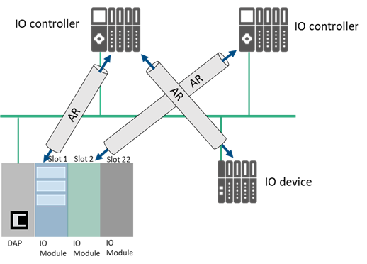
Figure 4 – Application and communication relationships
An IO controller can establish one AR each with multiple IO devices. Within an AR, several IO CRs on different APIs can be used for data exchange. This can be useful, for example, if more than one user profile (PROFIdrive, ENCODER etc.) is involved in communication and different submodules are required.