The Stuctured DataTypes in this chapter are formally defined in two different table formats.
One table format has the columns Name, Type and Description for the definition of standard OPC UA structures where all structure elements are mandatory and must be transported between OPC UA Client and Server.
The second table format has the columns Name, Type, Optional and Description for the definition of OPC UA structures with optional structure elements.
The following Figure 14 provides an overview of the Structure DataTypes defined for the AutoID Device access.
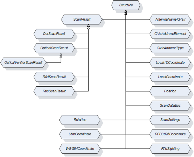
Figure 14 – Structure DataType overview
This DataType is a structure that defines a pair of RFID antenna ID and antenna name. Its composition is formally defined in Table 45.
Table 45 – AntennaNameIdPair Structure
|
Name |
Type |
Description |
|
AntennaNameIdPair |
Structure |
Subtype of Structure defined in OPC 10000-5. |
|
AntennaId |
Int32 |
ID of the antenna returned in the RfidSighting contained in the RfidScanResult. The RfidSighting is defined in 9.3.13. The RfidScanResult is defined in 9.3.12. |
|
AntennaName |
String |
Name of the antenna with the AntennaId. |
Its representation in the AddressSpace is defined in Table 46.
Table 46 – AntennaNameIdPair Definition
|
Attribute |
Value |
|||||
|
BrowseName |
AntennaNameIdPair |
|||||
|
IsAbstract |
False |
|||||
|
References |
NodeClass |
BrowseName |
DataType |
TypeDefinition |
Other |
|
|
Subtype of Structure defined in OPC 10000-5. |
||||||
This DataType is a structure that defines the location of an object in a Cartesian local coordinate system arbitrarily chosen during configuration of an RTLS system. Its composition is formally defined in Table 47.
Table 47 – LocalCoordinate Structure
|
Name |
Type |
Description |
|
LocalCoordinate |
Structure |
Subtype of Structure defined in OPC 10000-5. |
|
X |
Double |
The X – coordinate of the object’s position in the unit defined by the LengthUnit property of the AutoID Device. |
|
Y |
Double |
The Y – coordinate of the object’s position in the unit defined by the LengthUnit property of the AutoID Device. |
|
Z |
Double |
The Z – coordinate of the object’s position in the unit defined by the LengthUnit property of the AutoID Device. |
|
Timestamp |
UtcTime |
Timestamp in UtcTime |
|
DilutionOfPrecision |
Double |
DOP is a value for the variance of the measurements delivered by the location system. The calculation of the value depends on the underlying system and is vendor specific. Values should be in accordance with the implementations like in GNSS systems. |
|
UsefulPrecision |
Int32 |
Values for Easting, Northing, and Altitude should be rounded by the clien tapplication to the n-th position after the decimal point. It specifies the number of useful digits after the decimal place. |
Its representation in the AddressSpace is defined in Table 48.
Table 48 – LocalCoordinate Definition
|
Attribute |
Value |
|||||
|
BrowseName |
LocalCoordinate |
|||||
|
IsAbstract |
False |
|||||
|
References |
NodeClass |
BrowseName |
DataType |
TypeDefinition |
Other |
|
|
Subtype of Structure defined in OPC 10000-5. |
||||||
This DataType is a structure that defines the position and the size of a code or a plain text within an image (so-called code area, used by OCR and optical code readers). Its composition is formally defined in Table 49.
|
Name |
Type |
Description |
|
Position |
Structure |
Subtype of Structure defined in OPC 10000-5. |
|
PositionX |
Int32 |
X coordinate of the top-left edge of the code area (counting starts on the left side of the image) |
|
PositionY |
Int32 |
Y coordinate of the top-left edge of the code area (counting starts on the top side of the image) |
|
SizeX |
Int32 |
Horizontal size of the code area in pixel |
|
SizeY |
Int32 |
Vertical size of the code area in pixel |
|
Rotation |
Int32 |
The rotation of the code area |
Its representation in the AddressSpace is defined in Table 50.
Table 50 – Position Definition
|
Attribute |
Value |
|||||
|
BrowseName |
Position |
|||||
|
IsAbstract |
False |
|||||
|
References |
NodeClass |
BrowseName |
DataType |
TypeDefinition |
Other |
|
|
Subtype of Structure defined in OPC 10000-5. |
||||||
This DataType is a structure that defines the structure of the scanned data in Epc_1 format. Its composition is formally defined in Table 51.
Table 51 – ScanDataEpc Structure
|
Name |
Type |
Description |
Optional |
|
ScanDataEpc |
Structure |
Subtype of Structure defined in OPC 10000-5. |
|
|
PC |
UInt16 |
Protocol control information according to ISO/IEC 18000-3 Mode 3, ISO/IEC 18000-63 and GS1 EPCglobal™. |
False |
|
UId |
ByteString |
AutoID Identifier according to ISO/IEC 18000-3 Mode 3, ISO/IEC 18000-63 and GS1 EPCglobal™. |
False |
|
XPC_W1 |
UInt16 |
Extended protocol control word 1 according to ISO/IEC 18000-3 Mode 3, ISO/IEC 18000-63 and GS1 EPCglobal™. |
True |
|
XPC_W2 |
UInt16 |
Extended protocol control word 2 according to ISO/IEC 18000-3 Mode 3, ISO/IEC 18000-63 and GS1 EPCglobal™. |
True |
Its representation in the AddressSpace is defined in Table 52.
Table 52 – ScanDataEpc Definition
|
Attribute |
Value |
|||||
|
BrowseName |
ScanDataEpc |
|||||
|
IsAbstract |
False |
|||||
|
References |
NodeClass |
BrowseName |
DataType |
TypeDefinition |
Other |
|
|
Subtype of Structure defined in OPC 10000-5. |
||||||
This DataType is a structure that defines the settings for a scan execution. Its composition is formally defined in Table 53.
Table 53 – ScanSettings Structure
|
Name |
Type |
Description |
Optional |
|
ScanSettings |
Structure |
Subtype of Structure defined in OPC 10000-5. |
|
|
Duration |
Duration |
Duration of the scan operation in milliseconds. Duration is one of the termination conditions for the scan operation. The value 0 is infinite. The termination conditions are related to each other. If one of the conditions is fulfilled, the scan operation is stopped. |
False |
|
Cycles |
Int32 |
Duration of the scan operation in ‘number of scan cycles’. The parameter Cycles is one of the termination conditions for the scan operation. The value 0 is infinite. The termination conditions are related to each other. If one of the conditions is fulfilled, the scan operation is stopped. |
False |
|
DataAvailable |
Boolean |
If this value is set to True, the scan operation is completed as soon as scan data is available. If this value is set to False, only the other termination conditions are used. |
False |
|
LocationType |
LocationType Enumeration |
The requestsd type of the location information returned in the scan results. The LocationTypeEnumeration DataType is defined in 9.2.3. |
True |
Its representation in the AddressSpace is defined in Table 54.
|
Attribute |
Value |
|||||
|
BrowseName |
ScanSettings |
|||||
|
IsAbstract |
False |
|||||
|
References |
NodeClass |
BrowseName |
DataType |
TypeDefinition |
Other |
|
|
Subtype of Structure defined in OPC 10000-5. |
||||||
Table 54 – ScanSettings Definition
This DataType is a structure that defines the results of a scan. Its composition is formally defined in Table 55.
Table 55 – ScanResult Structure
|
Name |
Type |
Description |
Optional |
|
ScanResult |
Structure |
Subtype of Structure defined in OPC 10000-5. |
|
|
CodeType |
CodeTypeDataType |
Defines the format of the ScanData as string. The String DataType CodeTypeDataType and the predefined format strings are defined in 9.1.3. |
False |
|
ScanData |
ScanData |
Holds the information about the detected objects e.g. the detected transponders. The ScanData DataType is defined in 9.4.2. |
False |
|
Timestamp |
UtcTime |
Timestamp of the ScanResult creation. |
False |
|
Location |
Location |
Returns the location of the object detection. The Location DataType is defined in 9.4.1. |
True |
The ScanResult Structure representation in the AddressSpace is defined in Table 56.
Table 56 – ScanResult Definition
|
Attribute |
Value |
|||||
|
BrowseName |
ScanResult |
|||||
|
IsAbstract |
True |
|||||
|
References |
NodeClass |
BrowseName |
DataType |
TypeDefinition |
IsAbstract |
|
|
Subtype of Structure defined in OPC 10000-5. |
||||||
|
Has Subtype |
DataType |
OcrScanResult |
|
|
False |
|
|
Has Subtype |
DataType |
OpticalScanResult |
|
|
False |
|
|
Has Subtype |
DataType |
RfidScanResult |
|
|
False |
|
|
Has Subtype |
DataType |
RtlsLocationResult |
|
|
False |
|
This DataType is a structure that defines the results of an OCR reader device scan. Its composition is formally defined in Table 57.
Table 57 – OcrScanResult Structure
|
Name |
Type |
Description |
Optional |
|
OcrScanResult |
Structure |
Subtype of ScanResult defined in 9.3.8. |
|
|
ImageId |
NodeId |
NodeId of the original scan image file object used for this scan result. This image file is also available through the Images folder defined in 6.2.3.2. |
False |
|
Quality |
Byte |
Returns the probability of correct decoding. |
False |
|
Position |
Position |
Returns the position of the text within the image The Position DataType is defined in 9.3.5. |
False |
|
Font |
String |
Returns the font name used for decoding |
True |
|
DecodingTime |
UtcTime |
Returns the required decoding time |
True |
Its representation in the AddressSpace is defined in Table 58.
Table 58 – OcrScanResult Definition
|
Attribute |
Value |
|||||
|
BrowseName |
OcrScanResult |
|||||
|
IsAbstract |
False |
|||||
|
References |
NodeClass |
BrowseName |
DataType |
TypeDefinition |
Other |
|
|
Subtype of ScanResult defined in 9.3.8. |
||||||
This DataType is a structure that defines the results of a scan. Its composition is formally defined in Table 59.
Table 59 – OpticalScanResult Structure
|
Name |
Type |
Description |
Optional |
|
OpticalScanResult |
Structure |
Subtype of ScanResult defined in 9.3.8. |
|
|
Grade |
Float |
Returns the Grade of the 1D/2D code according to IEC 15415 (2D) and IEC 15416 (1D). The Grade is a value between 0 and 4 where 0 is the worst quality and 4 is the best quality. |
True |
|
Position |
Position |
Returns the position of the text within the image The Position DataType is defined in 9.3.5. |
True |
|
Symbology |
String |
Type of barcode per ISO/IEC 15424. Example: "]I1". |
True |
|
ImageId |
NodeId |
NodeId of the original scan image file object used for this scan result. |
True |
Its representation in the AddressSpace is defined in Table 60.
|
Attribute |
Value |
|||||
|
BrowseName |
OpticalScanResult |
|||||
|
IsAbstract |
False |
|||||
|
References |
NodeClass |
BrowseName |
DataType |
TypeDefinition |
IsAbstract |
|
|
Subtype of ScanResult defined in 9.3.8. |
||||||
|
Has Subtype |
DataType |
OpticalVerifierScanResult |
|
|
False |
|
Table 60 – OpticalScanResult Definition
This DataType is a structure that defines the results of a scan. Its composition is formally defined in Table 61.
Table 61 – OpticalVerifierScanResult Structure
|
Name |
Type |
Description |
Optional |
|
OpticalVerifierScanResult |
Structure |
Subtype of OpticalScanResult defined in 9.3.10. |
|
|
IsoGrade |
String |
This value contains the ISO grade, the aperture and the wavelength used. Example content: "2.7/10/660" With the '2.7' being the grade, the '10' being the measuring aperture that was used for the analysis and the '660' is the wavelength of light used to illuminate the code. If the grade is reported without aperture and wavelength, then it really is quite meaningless (a code measured with an '06' aperture can give a totally different result that one measured with a '20' aperture for instance). |
False |
|
RMin |
Int16 |
The minimum reflection value in percent (from a dark bar). Example: 6 |
False |
|
SymbolContrast |
Int16 |
The Symbol Contrast value (Rmax – Rmin) in percent. Example: 41 |
False |
|
ECMin |
Int16 |
The minimum Edge Contrast value in percent. Example: 31 |
False |
|
Modulation |
Int16 |
The modulation (ECmin / SC) value in percent. Example: 76 |
False |
|
Defects |
Int16 |
The defects value in percent. Example: 14 |
False |
|
Decodability |
Int16 |
The decodability value in percent. Example: 87 |
False |
|
Decode |
Int16 |
The decode content value in percent. Example: 100 |
False |
|
PrintGain |
Int16 |
The print gain value in percent (-4%). Example: -4 |
False |
Its representation in the AddressSpace is defined in Table 62.
Table 62 – OpticalVerifierScanResult Definition
|
Attribute |
Value |
|||||
|
BrowseName |
OpticalVerifierScanResult |
|||||
|
IsAbstract |
False |
|||||
|
References |
NodeClass |
BrowseName |
DataType |
TypeDefinition |
Other |
|
|
Subtype of OpticalScanResult defined in 9.3.10. |
||||||
This DataType is a structure that defines the results of a RFID reader device scan. Its composition is formally defined in Table 63.
Table 63 – RfidScanResult Structure
|
Name |
Type |
Description |
|
RfidScanResult |
Structure |
Subtype of ScanResult defined in 9.3.8. |
|
Sighting |
RfidSighting [ ] |
Returns additional information on the RFID-related properties of the scan event as array of RfidSightings. Each AutoID Identifier can be detected several times during a scan cycle. Each detection of the AutoID Identifier causes an entry into the Sightings array. The RfidSighting DataType is defined in 9.3.13. |
Its representation in the AddressSpace is defined in Table 64.
|
Attribute |
Value |
|||||
|
BrowseName |
RfidScanResult |
|||||
|
IsAbstract |
False |
|||||
|
References |
NodeClass |
BrowseName |
DataType |
TypeDefinition |
Other |
|
|
Subtype of ScanResult defined in 9.3.8. |
||||||
Table 64 – RfidScanResult Definition
This DataType is a structure that defines additional RFID-related information of an AutoID Identifier detection during a scan cycle. Its composition is formally defined in Table 65.
Table 65 – RfidSighting Structure
|
Name |
Type |
Description |
|
RfidSighting |
Structure |
Subtype of Structure defined in OPC 10000-5. |
|
Antenna |
Int32 |
Returns the number of the antenna which detects the RFID tag first. |
|
Strength |
Int32 |
Returns the signal strength (RSSI) of the transponder. Higher values indicate a better strength. |
|
Timestamp |
UtcTime |
Timestamp in UtcTime. |
|
CurrentPowerLevel |
Int32 |
Returns the current power level (unit according to parameter settings) |
Its representation in the AddressSpace is defined in Table 66.
Table 66 – RfidSighting Definition
|
Attribute |
Value |
|||||
|
BrowseName |
RfidSighting |
|||||
|
IsAbstract |
False |
|||||
|
References |
NodeClass |
BrowseName |
DataType |
TypeDefinition |
Other |
|
|
Subtype of Structure defined in OPC 10000-5. |
||||||
This DataType is a structure that defines the rotation (or heading) of an object relative to the base coordinate system. The format is ‘yaw, pitch, roll’ as defined for aircraft principal axes. Its composition is formally defined in Table 67.
|
Name |
Type |
Description |
|
Rotation |
Structure |
Subtype of Structure defined in OPC 10000-5. |
|
Yaw |
Double |
The yaw of the object, in the unit defined for rotational measurements, e. g. in radians between PI and –PI (or in deg between +180° and -180°). Rotation measured around a vertical axis. Reference (yaw = 0) is the X-axis of the coordinate system |
|
Pitch |
Double |
The pitch of the object, in the unit defined for rotational measurements, e. g. in radians between PI and –PI (or in deg between +180° and -180°). Rotation measured around a horizontal axis. Reference (pitch = 0) is the direction of the yaw on the horizontal plane of the coordinate system |
|
Roll |
Double |
The roll of the object, in the unit defined for rotational measurements, e. g. in radians between PI and –PI (or in deg between +180° and -180°). Rotation measured around a horizontal axis pointing in the direction defined by yaw, pitch |
Its representation in the AddressSpace is defined in Table 68.
|
Attribute |
Value |
|||||
|
BrowseName |
Rotation |
|||||
|
IsAbstract |
False |
|||||
|
References |
NodeClass |
BrowseName |
DataType |
TypeDefinition |
Other |
|
|
Subtype of Structure defined in OPC 10000-5. |
||||||
Table 68 – Rotation Definition
This DataType is a structure that defines the results that an RTLS device or system returns. It extends the ScanResult structure. Its composition is formally defined in Table 69.
The optional Location field defined in the ScanResult structure shall be included in RtlsLocationResults.
Table 69 – RtlsLocationResult Structure
|
Name |
Type |
Description |
Optional |
|
RtlsLocationResult |
Structure |
Subtype of ScanResult defined in 9.3.8. |
|
|
Speed |
Double |
The current speed above ground of the located object. The unit is defined by the SpeedUnit variable. |
True |
|
Heading |
Double |
The (geographical) direction the located object is moving in on a plane. The unit is defined by the RotationUnit variable, but note that the heading can be different from the rotation of the object. |
True |
|
Rotation |
Rotation |
The rotation of the object identified by the UId as defined in 9.3.14. |
True |
|
ReceiveTime |
UtcTime |
ReceiveTime provides the time the RTLS received the location information from the underlying device. |
True |
Its representation in the AddressSpace is defined in Table 70.
Table 70 – RtlsLocationResult Definition
|
Attribute |
Value |
|||||
|
BrowseName |
RtlsLocationResult |
|||||
|
IsAbstract |
False |
|||||
|
References |
NodeClass |
BrowseName |
DataType |
TypeDefinition |
Other |
|
|
Subtype of ScanResult defined in 9.3.8. |
||||||
This DataType is a structure that defines the georeferenced location of an object on the earth’s surface in latitude, longitude and altitude using the World Geodetic System’s (WGS84) reference frame. Its composition is formally defined in Table 71.
Table 71 – WGS84Coordinate Structure
|
Name |
Type |
Description |
|
WGS84Coordinate |
Structure |
Subtype of Structure defined in OPC 10000-5. |
|
N/S Hemisphere |
String |
‘N’ or ‘S’ for northern or southern hemisphere |
|
Latitude |
Double |
Latitude in the unit defined by the GeographicalUnit property of the DeviceLocation Variable of the AutoID Device defined in 6.1.3.12. |
|
E/W Hemisphere |
String |
‘E’ or ‘W’ for eastern or western hemisphere |
|
Longitude |
Double |
Longitude in the unit by the GeographicalUnit property of the DeviceLocation Variable of the AutoID Device defined in 6.1.3.12. |
|
Altitude |
Double |
Altitude in the unit by the GeographicalUnit property of the DeviceLocation Variable of the AutoID Device defined in 6.1.3.12. |
|
Timestamp |
UtcTime |
Timestamp in UtcTime |
|
DilutionOfPrecision |
Double |
DOP is a value for the variance of the measurements delivered by the location system. The calculation of the value depends on the underlying system and is vendor specific. Values should be in accordance with the implementations like in GNSS systems. |
|
UsefulPrecisionLatLon |
Int32 |
Values for Latitude and Longitude should be rounded by the client application to the n-th position after the decimal point. It specifies the number of useful digits after the decimal place. |
|
UsefulPrecisionAlt |
Int32 |
Values for Altitude should be rounded by the client application to the n-th position after the decimal point. It specifies the number of useful digits after the decimal place. |
Its representation in the AddressSpace is defined in Table 72.
|
Attribute |
Value |
|||||
|
BrowseName |
WGS84Coordinate |
|||||
|
IsAbstract |
False |
|||||
|
References |
NodeClass |
BrowseName |
DataType |
TypeDefinition |
Other |
|
|
Subtype of Structure defined in OPC 10000-5. |
||||||
Table 72 – WGS84Coordinate Definition
This DataType is a structure that defines the result values of an AutoID Identifier access of an AutoID device. Its composition is formally defined in Table 73.
Table 73 – AccessResult Structure
|
Name |
Type |
Description |
Optional |
|
AccessResult |
Structure |
Subtype of Structure defined in OPC 10000-5. |
|
|
CodeType |
CodeTypeDataType |
Defines the format of Identifier as string. The String DataType CodeTypeDataType and the predefined format strings are defined in 9.1.3. |
true |
|
Identifier |
ScanData |
The AutoID identifier (e.g. a code or a transponder) which was accessed by the command. The ScanData DataType is defined in 9.4.2. When this value exists, the value CodeType must be available too. |
true |
|
Timestamp |
UtcTime |
The point of time the AutoID Identifier was accessed by the command. |
true |
The AccessResult Structure representation in the AddressSpace is defined in Table 74.
Table 74 – AccessResult Definition
|
Attribute |
Value |
|||||
|
BrowseName |
AccessResult |
|||||
|
IsAbstract |
False |
|||||
|
References |
NodeClass |
BrowseName |
DataType |
TypeDefinition |
IsAbstract |
|
|
Subtype of Structure defined in OPC 10000-5. |
||||||
|
Has Subtype |
DataType |
RfidAccessResult |
|
|
False |
|
This DataType is a structure that defines the additional result values of a Rfid Transponder access of a Rfid reader device. Its composition is formally defined in Table 75.
Table 75 – RfidAccessResult Structure
|
Name |
Type |
Description |
Optional |
|
RfidAccessResult |
Structure |
Subtype of AccessResult defined in 9.3.17. |
|
|
CodeTypeRWData |
CodeTypeDataType |
Defines the format of RWData as string. The String DataType CodeTypeDataType and the predefined format strings are defined in 9.1.3. |
true |
|
RWData |
ScanData |
The user data which was written to / was read from the Rfid Transponder by the command. The ScanData DataType is defined in 9.4.2. When this value exists, the value CodeType must be available too. |
true |
|
Antenna |
Int32 |
The antenna by which the transponder was accessed by the command. |
true |
|
CurrentPowerLevel |
Int32 |
The power level with which the transponder was accessed by the command. |
true |
|
PC |
UInt16 |
The Protocol Control Word of the transponder accessed by the command. |
true |
|
Polarization |
String |
The Polarization with which the transponder was accessed by the command. |
true |
|
Strength |
Int32 |
The Rssi value with which the transponder was accessed by the command. |
true |
Its representation in the AddressSpace is defined in Table 76.
Table 76 – RfidAccessResult Definition
|
Attribute |
Value |
|||||
|
BrowseName |
RfidAccessResult |
|||||
|
IsAbstract |
False |
|||||
|
References |
NodeClass |
BrowseName |
DataType |
TypeDefinition |
Other |
|
|
Subtype of AccessResult defined in 9.3.17. |
||||||